Variable-step-pitch micro-milling repair tool path generation method for optical crystal surface damage points

A surface damage, optical crystal technology, applied in the direction of milling machine tools, milling machine equipment, manufacturing tools, etc., can solve problems such as damage to optical components

Active Publication Date: 2021-02-19
HARBIN INST OF TECH
View PDF6 Cites 2 Cited by
  • Summary
  • Abstract
  • Description
  • Claims
  • Application Information

AI Technical Summary

Problems solved by technology

In the actual use of KDP crystal components, the strong laser in the ICF optical path system is extremely sensitive to the residual knife marks with a constant period. Due to the interference and diffraction effects of the laser, the light intensity will be enhanced inside the KDP and inside the downstream fused silica optical components. Hot spots, which in turn cause new damage to optics

Method used


Image

  • Variable-step-pitch micro-milling repair tool path generation method for optical crystal surface damage points
  • Variable-step-pitch micro-milling repair tool path generation method for optical crystal surface damage points
  • Variable-step-pitch micro-milling repair tool path generation method for optical crystal surface damage points

Examples


Embodiment Construction

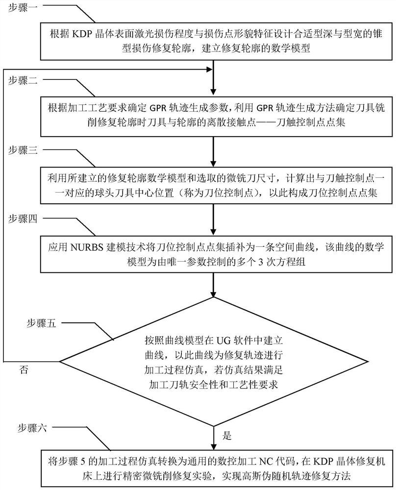
[0061] An example analysis of the generation of GPR micro-repair trajectory at the defect point on the surface of the KDP crystal element, using the above method according to figure 1 The process shown in the figure completes the experimental verification of the variable step-spacing repair trajectory generation method.

[0062] 1) According to the degree of laser damage on the surface of the KDP crystal and the shape characteristics of the damage point, a damage repair profile with a suitable depth and width is designed, and a mathematical model of the repair profile is established;

[0063] The laser damage experiment shows that the laser damage caused by ablation often occurs on the crystal surface, which is characterized by a large damage area and a shallow depth, and the tapered repair profile can better remove the damaged area. The optical simulation verification shows that the conical repair profile is a laser "friendly" repair profile, which can effectively improve th...


PUM


Abstract

The invention discloses a variable-step-pitch micro-milling repair tool path generation method for optical crystal surface damage points, and belongs to the technical field of optical material and optical element surface repair. The method aims to delay the modulation effect of a constant-period tool mark generated by a soft and brittle KDP crystal in micro-milling repair on incident laser, and achieve the purposes of improving the laser damage resistance of a KDP crystal element and prolonging the service life of the KDP crystal element. The method is characterized by: establishing a mathematical model of a repaired contour; determining discrete contact points of the cutter and the contour for controlling the motion trend of the pseudo-random trajectory when the cutter mills and repairs the contour by using a GPR trajectory generation method; utilizing the established repair contour mathematical model and the selected micro-milling cutter size; interpolating the cutter location control point set into a space curve by applying an NURBS modeling method; and establishing a curve in UG software according to the curve model, and performing machining process simulation by taking the curve as a repair track. It is verified that the method has a good elimination effect on the constant-period knife lines, and the strong laser damage resistance of the method is improved.

Description

technical field [0001] The invention belongs to the technical field of optical materials and optical element surface repair, and in particular relates to a variable step-pitch precision micro-milling repair process for laser damage points on the surface of a large-diameter KDP crystal element. Background technique [0002] In order to pursue reliable and controllable clean nuclear fusion energy, countries around the world have built large-scale laser-driven inertial confinement fusion facilities (ICF), such as the National Ignition Facility (NIF) in the United States and the Shenguang Laser Facility (SG) in China. In such a huge laser system, tens of thousands of large-aperture, high-precision, and high-quality optical components are required. Among them, the KDP functional crystal material should have unique optical properties and be used to make photoelectric switches and frequency doubling components, becoming an irreplaceable core device in the current laser-driven inert...

Claims


Application Information

Patent Timeline
Patent Type & Authority Applications(China)
IPC IPC(8): G05B19/19G05B19/4069
CPCG05B19/19G05B19/182G05B19/4069G05B2219/35349B28D5/0064B28D5/00G06F17/17G06F30/17B23C3/00B23C2226/42B23C2260/56B23C2265/08B28D5/007G06F17/11G06F17/16
Inventor 程健武文强陈明君刘启杨浩赵林杰谭超程旭盟刘赫男王廷章
Owner HARBIN INST OF TECH
Why Eureka
Try Eureka