
Eureka
For R&D, Eureka makes reading and utilizing patents & technical documents easy.
Eureka AIR
Designed for self-driven R&D workflows. Generate viable solutions, solve complex R&D challenges, empower your innovation with AI.

Eureka Materials
Designed for material experts only. Revolutionize your material R&D, from search, analyze, to developing new materials.

TechResearch
Generate reliable direction feasibility study reports for your R&D in just a few steps.

TechSeek
Discover and master advanced knowledge NOW. Basics, ideas, possibilities, all at once.

TechMind
As an expert in R&D Theories, TechMind can generates customized viable solutions instantly.

TechRisk
Analyze your overall solution with one click, know your potential R&D risks in advance.

TechMonitor
Get weekly tech updates, stay abreast of the latest tech innovations and key insights.
Method and arrangement for removing gas from a liquid
A technology for removing and gas, applied in the direction of liquid degassing, separation methods, chemical instruments and methods, etc., to achieve the effect of effective separation
- Summary
- Abstract
- Description
- Claims
- Application Information
AI Technical Summary
Problems solved by technology
Method used
Image

Examples
example 1
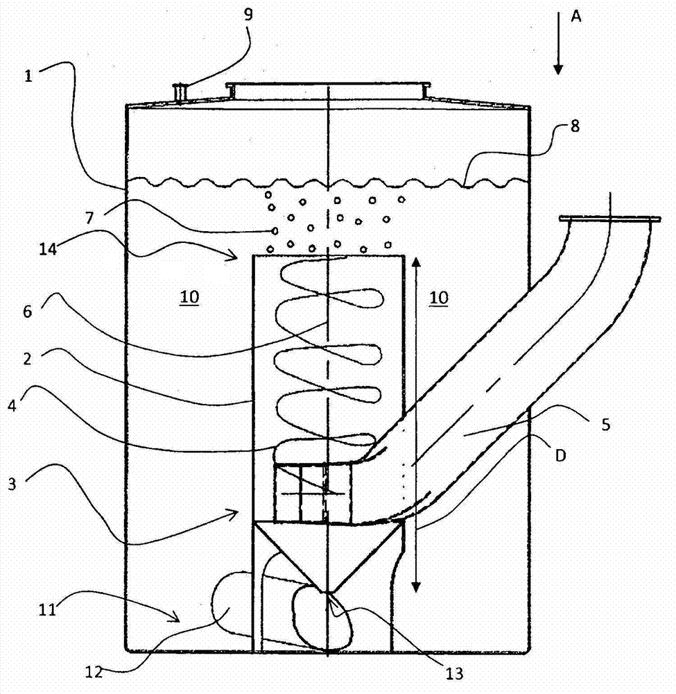
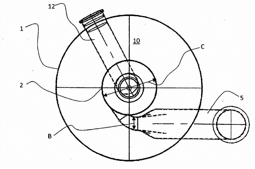
[0024] The functional capabilities of the devices according to the invention were tested under laboratory-level conditions. The device for degassing according to the invention is described in the following example. The degassing device according to this example comprises a degassing tank described in this example as a cyclone and a tank surrounding said cyclone. In the degassing plant according to this example the water is treated, in this case air is fed into the feed pipe of the cyclone. The cyclone is arranged concentrically in the tank so that the solution can be fed tangentially through the lower part of the cyclone. In this way, the solution undergoes a spiral upward movement in order to remove air bubbles at the top of the cyclone, some of which are carried along with the stream into the intermediate space between the tank and the cyclone. The cyclone used in the plant according to this example has a diameter of 300 mm and a height of 700 mm; these dimensions vary as ...
PUM
 Abstract
Description
Claims
Application Information
 - R&D Engineer
- R&D Manager
- IP Professional
- Industry Leading Data Capabilities
- Powerful AI technology
- Patent DNA Extraction
Browse by: Latest US Patents, China's latest patents, Technical Efficacy Thesaurus, Application Domain, Technology Topic, Popular Technical Reports.
© 2024 PatSnap. All rights reserved.Legal|Privacy policy|Modern Slavery Act Transparency Statement|Sitemap|About US| Contact US: help@patsnap.com