
Structural long-period optical fiber grating

A fiber grating, long-period technology, applied in the direction of cladding fiber, optical waveguide light guide, optical waveguide coupling, etc., can solve the problems of insufficient compact structure, single structure, harsh realization conditions, etc., and achieves simple composition structure and preparation process. The effect of reducing the number of grating periods and enriching the optical properties

Active Publication Date: 2012-10-24
JINAN UNIVERSITY
View PDF4 Cites 16 Cited by
  • Summary
  • Abstract
  • Description
  • Claims
  • Application Information

AI Technical Summary

Problems solved by technology

The preparation process of these preparation methods is very complicated, and the cost of preparation equipment such as lasers is relatively high.
Moreover, the length of the grating in the long-period fiber grating prepared by the traditional method is mostly on the order of centimeters, and its structure is not compact enough.
[0004] So far, all the long-period fiber gratings prepared by these traditional methods are formed by periodically modulating the refractive index on an optical fiber. The long-period gratings formed by these methods not only have a single structure, but also have a fixed form. After the grating is formed Its period is difficult to change; in addition, because the long-period fiber grating prepared by the traditional method only has the characteristic of band-stop filtering, it cannot realize the function of band-pass filter, which brings great inconvenience to the application
[0005] In the past, many attempts have been made to develop the band-pass filtering characteristics of long-period gratings. For example, the Chinese invention patent with the publication number CN 101446662A proposes a long-period fiber grating band-pass filter, which includes optical fibers and The optical fiber is connected, and there are microgrooves on the end faces of the optical fiber and the optical fiber to be connected. The optical fiber and the optical fiber to be connected are connected together by butt joints. The groove of the microgroove forms an FP cavity, and the cross section of the groove is smaller than the cross section of the core , the two ends of the FP cavity are respectively fabricated with long-period fiber gratings, but the bandpass filter needs to be realized by two long-period fiber gratings, and the two long-period grating wavelengths are required to be precisely aligned, and the realization conditions are compared harsh

Method used


Image

  • Structural long-period optical fiber grating
  • Structural long-period optical fiber grating
  • Structural long-period optical fiber grating

Examples


Embodiment

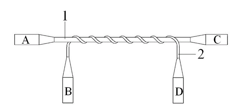
[0029] Such as figure 1 As shown, a structural long-period fiber grating includes a shaft 1 and a helix 2, and a periodic helical structure is formed by winding the helix 2 on the shaft 1, thereby obtaining a long-period fiber grating; it can be seen that the long-period fiber of this embodiment The composition structure and preparation process of the grating are very simple.

[0030] The shaft 1 and the helix 2 are micro-nano silica fibers, micro-nano glass fibers or micro-nano polymer fibers with a cross-sectional diameter of micron or nanometer order; the cross-sectional diameter of the shaft 1 is larger than that of the helix 2. Micro-nano silica optical fiber is obtained by melting and tapering of standard optical fiber; micro-nano glass optical fiber is obtained by melting and drawing of glass fiber or glass melting; micro-nano polymer optical fiber is obtained by melting and drawing of polymer optical fiber or polymer melting; Both ends of the micro-nano silica fiber, ...


PUM

PropertyMeasurementUnit
Cross section diameteraaaaaaaaaa
Pitchaaaaaaaaaa

Abstract

The invention discloses a structural long-period optical fiber grating. The structural long-period optical fiber grating comprises a shaft and a spiral line, wherein the spiral line is wound on the surface of the shaft to form a periodical spiral structure; the diameters of the cross sections of the shaft and the spiral line are in level of micron or nanometer; and the diameter of the cross section of the shaft is larger than that of the cross section of the spiral line. The structural long-period optical fiber grating disclosed by the invention has the advantages of being simple in manufacturing process, low in manufacturing cost, simple in structure, compact, smart and the like; and in addition, the structural long-period optical fiber grating can simultaneously realize functions of band pass filtering and band elimination filtering.

Description

technical field [0001] The invention belongs to the field of optical fiber technology, in particular to a structural long-period optical fiber grating. Background technique [0002] Long-period fiber gratings have an extremely important position in the field of communication and sensing and have many potential applications, such as gain flattening, dispersion compensation for fiber amplifiers, and temperature, strain, and biochemical sensors. The basic light transmission principle of long period fiber grating is to couple the forward-transmitted core mode with the high-order modes of each order in the same direction. Because it periodically modulates the conduction mode, the fundamental mode and high-order mode meet the resonance Energy conversion occurs under certain conditions, and the high-order mode is attenuated after a certain distance, forming a loss peak. [0003] At present, there are many methods to prepare long-period fiber gratings, such as long-period fiber gra...

Claims


Application Information

Patent Timeline
IPC IPC(8): G02B6/02G02B6/255
Inventor 孙立朋李杰关柏鸥
Owner JINAN UNIVERSITY
Learn More