
Passive lossless buffering circuit of power factor correction circuit

A technology of power factor correction and buffer circuit, applied in the direction of output power conversion devices, electrical components, etc., can solve the problems of reduced converter efficiency, large reverse recovery current, large electromagnetic noise, etc., and reduce reverse recovery loss. , the effect of improving the conversion efficiency

Active Publication Date: 2012-10-24
DONGGUAN MENTECH OPTICAL & MAGNETIC CO LTD
View PDF3 Cites 6 Cited by
  • Summary
  • Abstract
  • Description
  • Claims
  • Application Information

AI Technical Summary

Problems solved by technology

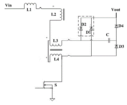
[0003] Electrical equipment such as converters have two operating modes, continuous current mode and discontinuous current mode. When the converter works in continuous current mode, there will be a commutation process in which the switching tube and the rectifier tube are in a common state when the switching tube is turned on. During the process, the current of the rectifier tube will turn to the switch tube sharply, and the current of the switch tube rises too fast to cause a large loss of the switch tube, and the current of the rectifier tube drops too fast, which may cause a large reverse recovery current, which eventually leads to a decrease in the efficiency of the converter and High electromagnetic noise and other adverse effects

Method used


Image

  • Passive lossless buffering circuit of power factor correction circuit

Examples


Embodiment Construction

[0012] In order to further understand the features, technical means, and specific objectives and functions achieved by the present invention, the present invention will be further described in detail below in conjunction with the accompanying drawings and specific embodiments.

[0013] Such as figure 1 As shown, the passive lossless buffer circuit of a power factor correction circuit in the present invention includes a main boost inductor L1, a secondary boost inductor L2, a first auxiliary coupling inductor L3, a second auxiliary coupling inductor L4, a main power switch S, and a buffer Capacitor C, first diode D1, second diode D2, third diode D3 and fourth diode D4, one end of the main boost inductor L1 is connected to a voltage input terminal Vin, the main boost The other end of the piezoelectric inductor L1 is electrically connected to the same-named end of the secondary boosting inductor L2, and the non-identical end of the secondary boosting inductor L2 is electrically c...


PUM


Abstract

The invention discloses a passive lossless buffering circuit of a power factor correction circuit. The passive lossless buffering circuit comprises boost inductors, auxiliary coupling inductors, a main power switch, a buffering capacitor and fast recovery diodes, wherein a main boost inductor and a secondary boost inductor are connected; the secondary boost inductor is connected with a first auxiliary coupling inductor and one end of a second auxiliary coupling inductor; the other end of the second auxiliary coupling inductor, a first diode anode, a third diode anode and the main power switch are connected; the other end of the first auxiliary coupling inductor, a second diode anode and one end of the buffering capacitor are connected; the other end of the buffering capacitor and a third diode cathode are connected; the connection point of the buffering capacitor and the third diode is connected with a fourth diode anode; and the cathodes of the first diode, the second diode and the fourth diode are electrically connected. With the adoption of the passive lossless buffering circuit of the power factor correction circuit, the reverse recovery problem of the diode can be effectively controlled, the switching loss is reduced, the reverse recovery energy can be stored by the buffering capacitor and the energy is transmitted to a load, so that the conversion efficiency is improved, and at the same time, the electromagnetic interference of electric equipment is effectively reduced.

Description

technical field [0001] The invention relates to the field of switching power supplies, in particular to a passive lossless snubber circuit of a power factor correction circuit. Background technique [0002] Mains power is an energy source that our life cannot do without, and many electrical equipment will generate a lot of harmonic interference due to various reasons, which will have a lot of impact on the city power grid. [0003] Electrical equipment such as converters have two operating modes, continuous current mode and discontinuous current mode. When the converter works in continuous current mode, there will be a commutation process in which the switching tube and the rectifier tube are in a common state when the switching tube is turned on. During the process, the current of the rectifier tube will turn to the switch tube sharply, and the current of the switch tube rises too fast to cause a large loss of the switch tube, and the current of the rectifier tube drops to...

Claims


Application Information

Patent Timeline
IPC IPC(8): H02M1/34
Inventor 江晓东
Owner DONGGUAN MENTECH OPTICAL & MAGNETIC CO LTD
Learn More