A switching power supply based on mos tube
A technology of MOS tube and switching power supply, which is applied in the field of switching power supply based on MOS tube, can solve the problems of switching power supply protection loopholes, clamping diodes that easily increase power conversion power loss, and high requirements for clamping diodes, so as to improve intelligence and safety. performance, reduce operating losses and switching noise, and reduce requirements
- Summary
- Abstract
- Description
- Claims
- Application Information
AI Technical Summary
Problems solved by technology
Method used
Image
Examples
Embodiment 1
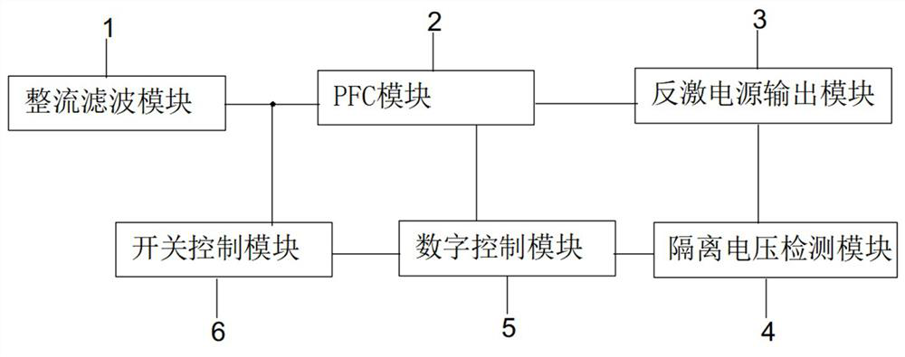
[0017] Example 1: see figure 1 , an embodiment of the present invention provides a switching power supply based on a MOS tube. The switching power supply based on a MOS tube includes: a rectification filter module 1, a PFC module 2, a flyback power output module 3, an isolation voltage detection module 4, and a digital control module 5 , switch control module 6;
[0018] Specifically, the rectification filter module 1 is used to convert the input alternating current into smooth direct current;
[0019] The PFC module 2 is connected to the rectification filter module 1 and the flyback power output module 3, and is used to control the direct current output by the rectification filter module 1 to be converted into a high-frequency pulse voltage and input to the flyback power output module 3, using It is used to detect the current signal during operation, and is used to reduce the operating loss and switching noise of the RCD clamp circuit during operation through the auxiliary s...
Embodiment 2
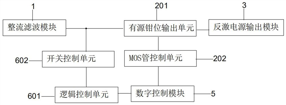
[0025] Example 2: On the basis of Example 1, please refer to figure 2 , in a specific embodiment of the MOS transistor-based switching power supply described in the present invention, the PFC module 2 includes an active clamp output unit 201 and a MOS transistor control unit 202;
[0026] Specifically, the MOS tube control unit 202 is used to control the direct current output from the rectification filter module 1 to be converted into a high-frequency pulse voltage and input to the flyback power output module 3 to detect the current signal during operation;
[0027] The active clamp output unit 201 is used to reduce the operating loss and switching noise of the RCD clamp circuit during operation through the auxiliary switch;
[0028] The input end of the active clamp output unit 201 is connected to the output end of the rectification filter module 1 , the control end of the active clamp output unit 201 is connected to one end of the MOS tube control unit 202 , and the output ...
Embodiment 3
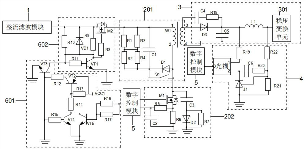
[0035] Example 3: On the basis of Example 2, please refer to image 3 , in a specific embodiment of the MOS transistor-based switching power supply according to the present invention, the active clamp output unit 201 includes a first resistor R1, a second resistor R2, a third resistor R3, a fourth resistor R4, a first capacitor C1, a first diode D1, a transformer W1, and an intelligent switch S1;
[0036] Specifically, one end of the first resistor R1, one end of the third resistor R3 and one end of the first capacitor C1 are all connected to the first end of the transformer W1, and the other end of the first resistor R1 is connected to the other end of the third resistor R3 , one end of the second resistor R2 and one end of the fourth resistor R4, the other end of the second resistor R2 and the other end of the fourth resistor R4 are connected to the other end of the first capacitor C1, the cathode of the first diode D1 and the intelligent One end of the switch S1 and the ot...
PUM
 Abstract
Description
Claims
Application Information
 - R&D
- Intellectual Property
- Life Sciences
- Materials
- Tech Scout
- Unparalleled Data Quality
- Higher Quality Content
- 60% Fewer Hallucinations
Browse by: Latest US Patents, China's latest patents, Technical Efficacy Thesaurus, Application Domain, Technology Topic, Popular Technical Reports.
© 2025 PatSnap. All rights reserved.Legal|Privacy policy|Modern Slavery Act Transparency Statement|Sitemap|About US| Contact US: help@patsnap.com


