
Solar energy temperature difference power generation system based on liquid metal thermal switch

A liquid metal, thermoelectric power generation technology, applied in the direction of generators/motors, electrical components, etc., can solve the problems that the output electric energy cannot be accumulated, and the utilization efficiency of thermoelectric heat energy is not high, so as to improve the energy conversion efficiency, the driving power is small, and the system is high The effect of energy efficiency

Active Publication Date: 2014-12-03
CHONGQING UNIV
View PDF6 Cites 0 Cited by
  • Summary
  • Abstract
  • Description
  • Claims
  • Application Information

AI Technical Summary

Problems solved by technology

[0005] Aiming at the above-mentioned deficiencies in the prior art, the purpose of the present invention is to overcome the disadvantages of low utilization efficiency of the existing temperature difference heat energy, and when the temperature of the heat source is too low, its output electric energy cannot be accumulated, and to provide a stable output electric energy and temperature difference heat energy Solar thermoelectric power generation system based on liquid metal thermal switch with high utilization efficiency

Method used


Image

  • Solar energy temperature difference power generation system based on liquid metal thermal switch
  • Solar energy temperature difference power generation system based on liquid metal thermal switch

Examples


Embodiment Construction

[0021] The present invention will be described in further detail below in conjunction with the accompanying drawings and specific embodiments.

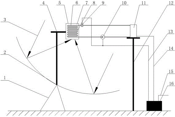
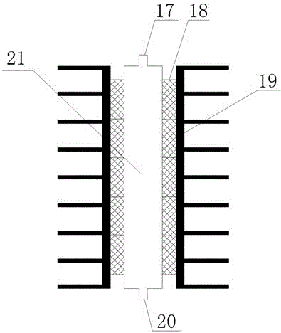
[0022] see Figure 1~2 , a solar thermoelectric power generation system based on liquid metal thermal switches, including:

[0023] The solar concentrator 2 is a focusing structure for collecting solar energy and transferring heat energy to the heat storage device 5;

[0024] The heat storage device 5 is mainly composed of a coil 8 filled with liquid metal 6 and a heat storage material 7 arranged outside the coil for collecting heat energy;

[0025] The thermoelectric power generation assembly 11 is mainly composed of a hot end flow channel 21, a thermoelectric power generation module 18 and a radiator 19; the hot end flow channel 21 is a rectangular channel structure, and its outer wall is a thermoelectric power generation module 18; A radiator 19 is provided; the upper and lower ends of the hot end flow channel 21 are respectively...


PUM


Abstract

The invention discloses a solar energy temperature difference power generation system based on a liquid metal thermal switch. The system comprises a solar energy condenser, a thermal storage device, a temperature difference power generating component and an electric power storage and control device, wherein one communication pipeline is arranged between one end of a coiled pipe of the thermal storage device and a liquid metal inlet of a hot end flowing channel, one communication pipeline is arranged between the other end of the coiled pipe of the thermal storage device and a liquid metal outlet of the hot end flowing channel, consequently a loop circuit is formed, a temperature control valve is arranged on the communication pipeline which connects the coiled pipe and the liquid metal inlet of the hot end flowing channel, an electromagnetic pump is arranged on the communication pipeline which connects the coiled pipe and the liquid metal outlet of the hot end flowing channel, the temperature control valve and the electromagnetic pump are connected with the electric power storage and control device through a signal and electrical energy transmission wire, a temperature difference power generation module is connected with the electric power storage and control device through a power storage wire, and the electric power storage and control device is further provided with a wire used for outputting electrical energy outwards. The system has the advantages that the problems that in prior art, the output electrical energy is unstable, the utilization efficiency of the temperature difference thermal energy is low and the like are solved, and the power generation module can be operated under the condition near the optimum working condition as far as possible.

Description

technical field [0001] The invention relates to a semiconductor thermoelectric power generation device utilizing solar energy, in particular to a solar thermoelectric power generation system based on a liquid metal thermal switch, which belongs to the application field of new energy technologies. Background technique [0002] In 1821, German physicist Seebeck discovered that in a closed circuit composed of two different metals (or semiconductors), when the temperatures at the two contacts are different, an electric potential will be generated in the circuit, which is the thermoelectric effect. Also known as the "Seebeck effect". After his comparative study of many materials, he laid the foundation for future thermoelectric research. In 1885, Rayleigh (Rayleigh) studied the possibility of using thermoelectric phenomenon to generate electricity, until Germany's Altenkirch (Altenkirch) proposed the principle of thermoelectric power generation: better thermoelectric materials m...

Claims


Application Information

Patent Timeline
Patent Type & Authority Patents(China)
IPC IPC(8): H02N11/00
Inventor 苟小龙欧强肖恒
Owner CHONGQING UNIV
Learn More