Electroluminescent anode, electroluminescent device and preparation method thereof

An electroluminescent device and luminescent technology, which is applied in the direction of electric solid-state devices, semiconductor/solid-state device manufacturing, electrical components, etc., can solve the problems of low hole injection efficiency and low transmittance of electroluminescent anodes, and achieve transparent The effect of improving the light effect, improving the light extraction efficiency, and simplifying the preparation process

Inactive Publication Date: 2012-10-31
OCEANS KING LIGHTING SCI&TECH CO LTD +1
View PDF5 Cites 11 Cited by
  • Summary
  • Abstract
  • Description
  • Claims
  • Application Information

AI Technical Summary

Problems solved by technology

[0003] In view of this, an embodiment of the present invention provides an electroluminescence anode to solve the technical problems of low light transmittance and low hole injection efficiency of the existing electroluminescence anode

Method used


Image

  • Electroluminescent anode, electroluminescent device and preparation method thereof
  • Electroluminescent anode, electroluminescent device and preparation method thereof
  • Electroluminescent anode, electroluminescent device and preparation method thereof

Examples


preparation example Construction

[0040] The embodiment of the present invention also provides the above electroluminescent device preparation method, comprising the following steps:

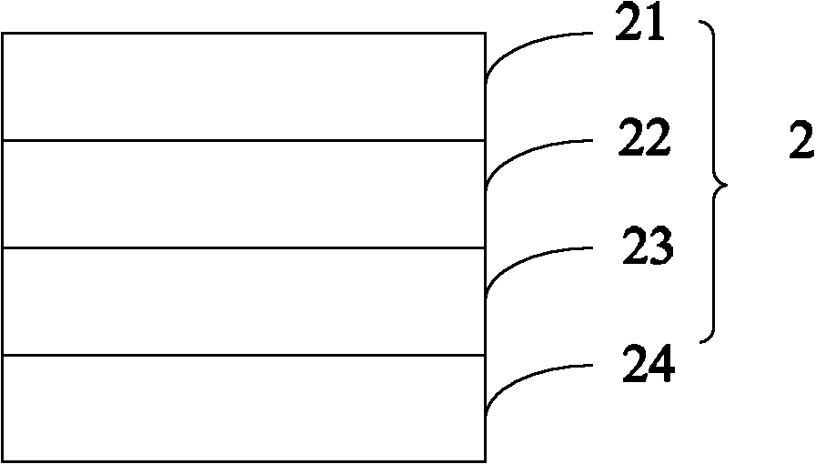
[0041] Form the cathode on the substrate by sputtering, evaporation or spin coating;

[0042] Forming a light-emitting layer on the cathode by sputtering, evaporation or spin coating;

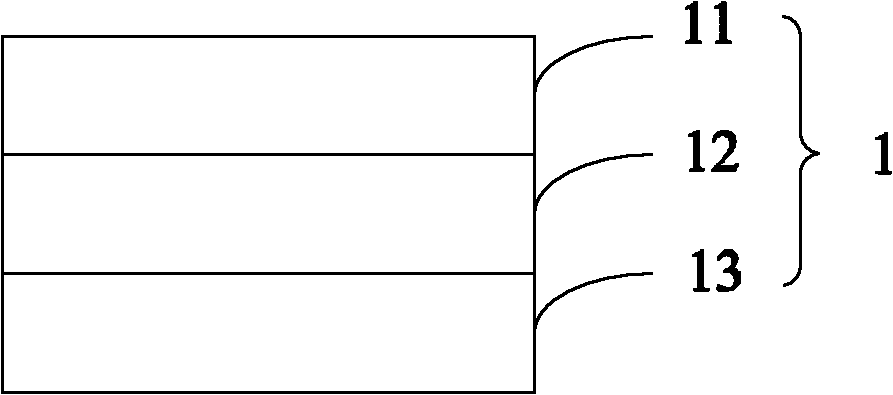
[0043] forming a first dielectric layer by sputtering, evaporating or spin-coating a hole-injecting metal oxide on the light-emitting layer;

[0044] forming a metal layer on the first dielectric layer by sputtering, evaporation or spin coating;

[0045] The hole-injecting metal oxide is sputtered, evaporated or spin-coated on the metal layer to form a second dielectric layer to obtain an electroluminescence device.

[0046] Further, the preparation method of the embodiment of the present invention also includes a cleaning step of the substrate before preparing the cathode, specifically: sequentially using detergent, deionized water, acetone, e...

Embodiment 1

[0052] The ITO glass is photolithographically processed, cut into the required light-emitting area, and then ultrasonically cleaned with detergent, deionized water, acetone, ethanol, and isopropanol for 15 minutes each to remove organic pollutants on the glass surface;

[0053] Evaporate and form silver cathode on the cleaned ITO glass;

[0054] Evaporate on the silver cathode to form Bphen:CsN 3 Electron injection layer;

[0055] Evaporating and forming a Bphen electron transport layer on the electron injection layer;

[0056] Evaporating and forming a TPBi hole blocking layer on the electron transport layer;

[0057] Evaporate and form Alq on the hole blocking layer 3 luminous layer;

[0058] Evaporating and forming a TAPC electron blocking layer on the light-emitting layer;

[0059] Evaporating and forming a NPB hole transport layer on the electron blocking layer;

[0060] Evaporate and form MoO on the hole transport layer 3 The first dielectric layer has a thickness...

Embodiment 2

[0064] The manufacturing method of the electroluminescent device in the embodiment of the present invention follows the first embodiment, wherein the thickness of the first dielectric layer is 20 nanometers.


PUM

PropertyMeasurementUnit
thicknessaaaaaaaaaa
thicknessaaaaaaaaaa
thicknessaaaaaaaaaa

Abstract

The invention is suitable for the technical field of photoelectricity, and provides an electroluminescent anode, an electroluminescent device and a preparation method thereof. The electroluminescent anode comprises a first medium layer, a second medium layer and a metal layer which are stacked. The metal layer is located between the first medium layer and the second medium layer. The first medium layer and the second medium layer are made of hole-injection metallic oxides. The metal layer is made of light-permeable metal. By the aid of the structure of the first medium layer/the metal layer/the second medium layer, the electroluminescent anode is fine in light permeability. By using the hole-injection metallic oxides, hole-injection performance of the anode is improved evidently, and the electroluminescent anode has excellent hole-injection performance under the premise of having high conductivity and high light permeability.

Description

technical field [0001] The invention belongs to the field of optoelectronic technology, and in particular relates to an electroluminescence anode, an electroluminescence device and a preparation method thereof. Background technique [0002] OLED (Electroluminescent Device) luminescence is a commonly used backlight source at present. OLED can be divided into bottom emission type and top emission type according to the light extraction method. The light of top emission organic electroluminescent device is extracted from the top; OLED devices can be divided into forward type and inverted type according to the order of preparation. At present, the anode of the inverted OLED is used as the light-emitting surface, and there are technical problems of low light transmission efficiency and low hole injection efficiency. Contents of the invention [0003] In view of this, an embodiment of the present invention provides an electroluminescent anode to solve the technical problems of l...

Claims


Application Information

Patent Timeline
Patent Type & Authority Applications(China)
IPC IPC(8): H01L51/52H01L51/50H01L51/56
Inventor 周明杰王平黄辉陈吉星
Owner OCEANS KING LIGHTING SCI&TECH CO LTD
Why Eureka
Try Eureka