Metal cutting wire with spiral wave-shaped rotary bending parts

A bending part and wire technology, which is applied in the field of composite rotating waveform cutting wire, can solve problems such as metal monofilament breakage, jewel line mark defects, affecting cutting speed and slicing quality, and achieve the goal of improving surface quality and reducing wear Effect

Inactive Publication Date: 2012-11-07
ZHENJIANG NAISI ADVANCE MATERIALS
View PDF7 Cites 23 Cited by
  • Summary
  • Abstract
  • Description
  • Claims
  • Application Information

AI Technical Summary

Problems solved by technology

[0003] The linear metal monofilament can only be mechanically brought into the mortar through the smooth surface at high speed, and during the cutting process, the abrasive in the mortar is easy to peel off from the cutting wire, which affects the cutting speed and slice quality, resulting in the cutting process. Silicon materials, gemstones and other hard materials are likely to cause metal monofilament breakage, silicon materials, gemstones and other hard materials such as line marks on the surface of slices and other quality or process problems

Method used


Image

  • Metal cutting wire with spiral wave-shaped rotary bending parts
  • Metal cutting wire with spiral wave-shaped rotary bending parts
  • Metal cutting wire with spiral wave-shaped rotary bending parts

Examples


Embodiment 1

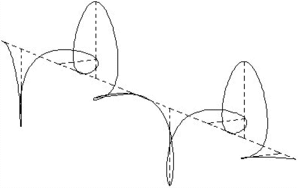
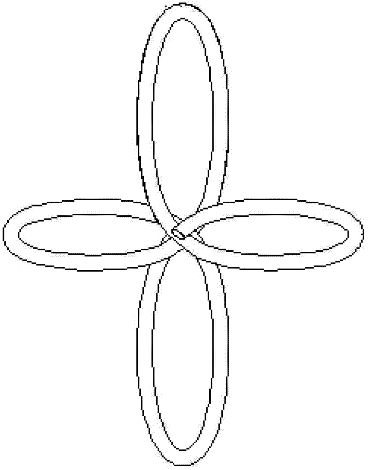
[0022] Such as Figure 1~2 As shown, a cutting wire with a helical wave-shaped rotating bending part has a diameter of 0.115mm and is provided with a plurality of spiral-wave rotating bending parts along the central axis. There are two types of rotating bending parts, and the two rotating The wave heights A1 of the bending part are different, respectively 0.23mm and 0.575mm; and the wavelength W of a single rotating bending part is 3.6mm, the rotating bending parts of the two different wave heights appear alternately, and the rotating bending part is farthest from the central axis The vertical line from the point to the central axis is evenly distributed along the meridian direction of the central axis, such as figure 2 As shown, the four vertical lines in one cycle are in the shape of a cross, and their included angle is 90°.

Embodiment 2

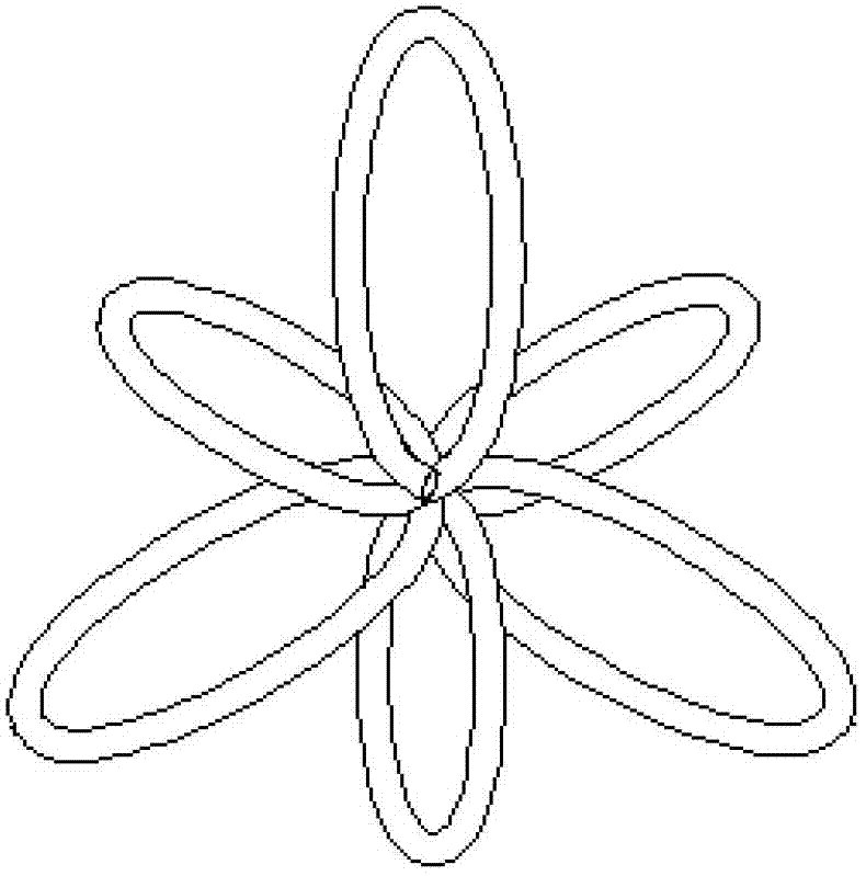
[0024] Such as image 3 As shown, the cutting wire in this embodiment is provided with two kinds of rotating bending parts with different wave heights A1. The perpendicular line from the farthest point of the axis to the central axis is evenly distributed along the meridional direction of the central axis, such as image 3 As shown, the 6 vertical lines in one period are evenly distributed, and the angle between them is 60°; the diameter of the metal wire is 0.25mm, and the wavelength of a single rotating bend is 5mm.

Embodiment 3

[0026] Such as Figure 4 As shown, the difference between the cutting wire in this embodiment and Embodiment 2 is: the diameter of the wire is 2mm, the wavelength of a single rotating bending part is 15mm, and the values ​​of two different wave heights A1 are 4mm and 10mm respectively, and There are 8 single rotating curved parts in one cycle, and the included angle between the farthest point of each rotating curved part from the central axis and the perpendicular to the central axis is 45°.


PUM

PropertyMeasurementUnit
diameteraaaaaaaaaa
wavelengthaaaaaaaaaa
diameteraaaaaaaaaa

Abstract

The invention discloses a metal cutting wire with spiral wave-shaped rotary bending parts. The metal cutting wire is provided with a plurality of spiral wave-shaped rotary bending parts along a central axis. According to the metal cutting wire with the spiral wave-shaped rotary bending parts, better capability of carrying mortar grinding materials in the hard material cutting process can be provided through a three-dimensional structure, and the grinding materials are unlikely to strip from the cutting wire so that the production speed in the cutting and fragmenting process of silicon, jewel and the like is greatly increased, the production efficiency in the cutting and fragmenting process of silicon, jewel and the like is greatly improved, and the surface quality of the fragmented materials also can be effectively improved at the same time. The speed of the grinding materials in the abrasion cutting process of hard materials is reduced relative to that of the metal cutting wire, so that the abrasion degree of the metal cutting wire is reduced.

Description

technical field [0001] The invention relates to a cutting wire, in particular to a cutting wire with a composite rotating waveform. Background technique [0002] In the division and slicing process of hard materials such as monocrystalline silicon, polycrystalline silicon, and gemstones in the field of electronics and solar energy, the most used method is to use linear metal monofilaments to move in one direction or reciprocating under a certain tension. way to split slices. When the metal monofilament is moving, through the mortar transportation and injection system, before the metal monofilament contacts with the silicon rod and other objects to be cut, the mortar containing extremely hard abrasive particles is sprayed on the metal monofilament, and the metal monofilament is brought into the cutting process. Through the continuous grinding process of extremely high hardness abrasive particles and silicon rods, gemstones and other objects to be cut, the cutting and slicing...

Claims


Application Information

Patent Timeline
Patent Type & Authority Applications(China)
IPC IPC(8): B28D5/04
Inventor 闵学刚
Owner ZHENJIANG NAISI ADVANCE MATERIALS
Why Eureka
Try Eureka