Direct drive wind turbine with a thermal control system

一种风力涡轮机、驱动型的技术,应用在控制机械能、风力发动机、风力电机组合等方向,能够解决不充分、风力涡轮机中油泄漏、油润滑系统复杂等问题,达到避免热压缩、提高可靠性和寿命、避免热膨胀的效果

Active Publication Date: 2012-11-07
SIEMENS GAMESA RENEWABLE ENERGY AS
View PDF5 Cites 16 Cited by
  • Summary
  • Abstract
  • Description
  • Claims
  • Application Information

AI Technical Summary

Problems solved by technology

To cool the large main bearings of direct drive wind turbines, oil exchange is limited and insufficient
Also, oil lubrication systems for integrated cooling are complex and there is always a risk of oil leakage in wind turbines, which should be avoided
[0006] No cooling system is known for grease lubricated bearings

Method used


Image

  • Direct drive wind turbine with a thermal control system
  • Direct drive wind turbine with a thermal control system
  • Direct drive wind turbine with a thermal control system

Examples


Embodiment Construction

[0041] In the following detailed description, reference is made to the accompanying drawings, which form a part hereof, and in which are shown, for purposes of illustration, specific embodiments in which the invention may be practiced. In this regard, directional terms such as "top" or "bottom" etc. are used with reference to the orientation of the figure(s) being described. Because components of an embodiment may be positioned in a number of different orientations, directional terms are used for purposes of illustration and are in no way limiting. It is to be understood that other embodiments may be utilized and structural or logical changes may be made without departing from the scope of the present invention. Therefore, the following detailed description is not to be taken in a limiting sense, but the scope of the invention is defined by the appended claims.

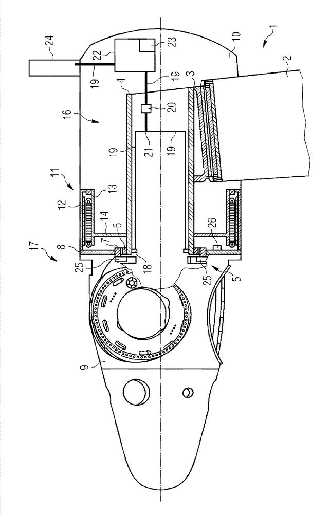
[0042] The wind turbine 1 has a tower 2 which is fixed to the ground and carries the entire structure of the wind ...


PUM


Abstract

A direct drive wind turbine with a thermal control system (15) has a generator (11) with a rotor (12) and a stator (13), and a bearing (5) with an inner ring (6) and an outer ring (7) connecting the rotor (12) and the stator (13) rotatively. The thermal control system (15) comprises a cooling system (16) and a heating system (17). The cooling system (16) comprises at least one heat sink (18) which is in thermal communication with the inner ring (6) of the bearing (5), and a heat dissipater (24) which is in thermal communication with the heat sink (18). The heating system (17) comprises at least one heating element (25) being in thermal communication with the outer ring (7) of the bearing (5).

Description

technical field [0001] The present invention relates to thermal management of wind turbine bearings. In particular, the present invention relates to a direct drive wind turbine with a thermal control system, a bearing assembly and a method for controlling bearing temperature. Background technique [0002] The bearings of wind turbines have a clearance of approximately -0.1 to 0.2 mm. In order to control the lifetime and air gap of the generator, it is advantageous to control the gap. The problem is that the inner ring of the bearing expands due to heat, reducing the life of the bearing. The reason for the heating is the small mass / stiffness of the inner ring of the bearing as it is constructed with the shaft compared to the mass / stiffness of the outer ring. [0003] For an outer rotor / inner stator generator, the thermal difference will be even higher due to the high mass of the blade hub and the rotor yoke attached to the outer ring. Additionally, the hub and yoke struct...

Claims


Application Information

Patent Timeline
Patent Type & Authority Applications(China)
IPC IPC(8): F03D9/00F03D11/00F16C37/00
CPCF16C37/00Y02E10/725H02K2213/09H02K9/19H02K7/086H02K15/125H02K7/1838F05B2220/7066H02K2201/03Y02E10/722H02K5/1735F16C37/007H02K5/1737F03D11/0008F05B2260/20F03D80/70F16C2300/14F03D80/60F16C2360/31Y02E10/72F03D80/00
Inventor U.埃里克森S.索伦森
Owner SIEMENS GAMESA RENEWABLE ENERGY AS
Why Eureka
Try Eureka