Prefabricated framework infilled wall

A technology for filling walls and skeletons, applied to walls, building components, buildings, etc., can solve the problems of low strength of filling walls, high cost of main structure, complicated construction technology, etc., and achieve fast wall formation, low overall cost, and on-site construction The effect of simple process

Inactive Publication Date: 2012-11-14
贵州皆盈科技开发有限公司
View PDF4 Cites 6 Cited by
  • Summary
  • Abstract
  • Description
  • Claims
  • Application Information

AI Technical Summary

Problems solved by technology

The existing problem is that, with the shortage of human resources in our country, the cost of labor has doubled, and the cost of the existing filling wall has been greatly improved. In addition, the low strength of the filling wall of aerated concrete blocks is not conducive to safety and security. Pa

Method used


Image

  • Prefabricated framework infilled wall
  • Prefabricated framework infilled wall
  • Prefabricated framework infilled wall

Examples


Embodiment 1

[0027] like Figure 13 The circular arc waveform prefabricated skeleton 1 (vertical length 2900, width 1000 including 5 waves, arch height 60, wall thickness 20) is delivered to the construction site after being prefabricated in the factory, and filled in the wall according to the middle distance of 1050 and the gap width of 50 The buckle arrangement in the axial plane is fixed on the upper and lower floors with expansion bolts. The corrugated metal tire net 6 (thickness 30, wave width 50) is prefabricated in the factory and delivered to the construction site. Vertical to the height direction of the skeleton 1, the pipeline is laid in the cavity in two directions, the cement sand is dry-mixed according to the ratio of 1:2, and then packed and transported to the construction site. 20 thick on the rib 4 and the tire net 6, after reaching a certain strength, the surface layer 2 is now smeared with 15 thick vitrified microbead thermal insulation mortar, and the surface is scraped ...

Embodiment 2

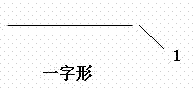
[0029] like Figure 14 The L-shaped prefabricated skeleton 1 shown (vertical length 2900, long leg 1000, short leg 100, wall thickness 20) is delivered to the construction site after prefabricated in the factory, and every two anti-symmetric buckles are combined, according to the middle distance 1050 and the gap width 50 are arranged in the central axis plane of the filling wall and fixed on the upper and lower floors with expansion bolts, the pipeline is laid in the vertical rib 4 and the surface layer 2, and the cement sand is dry-mixed according to the ratio of 1:2 and then packed in bags and delivered to construction On site, apply or spray on the outer side of the vertical rib 4 and the wall at a thickness of 20 thick, and the prepared desulfurized gypsum that has been retarded for 30 minutes is transported to the construction site, add water and mix well, and then apply or spray on the inner side of the wall at a thickness of 20 After reaching a certain strength, the sur...

Embodiment 3

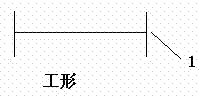
[0031] like Figure 15 The W-shaped prefabricated frame 1 shown (vertical length 2900, width 1000, arch height 60, wall thickness 20) is delivered to the construction site after being prefabricated in the factory. The front and back are arranged staggeredly and fixed on the upper and lower floors with expansion bolts. The retarded phosphogypsum is transported to the construction site. After adding water and stirring well, it is now painted or sprayed on both sides of the prefabricated skeleton 1. The total thickness is 90. After reaching a certain strength, the surface Just scrape the putty. This example is for an interior partition wall.


PUM


Abstract

The invention provides a prefabricated framework infilled wall, which comprises prefabricated frameworks (1), wherein the prefabricated frameworks (1) are transversely arranged along the horizontal direction, and gaps (3) are arranged between adjacent prefabricated frameworks (1). Vertical ribs (4) are arranged in the gaps (3), and face layers (2) are arranged on two outer layers of the prefabricated frameworks (1). The prefabricated framework infilled wall is superior to the existing aerated concrete building block infilled walls and hollow internal model metal net cement internal parting walls in terms of comprehensive economic indicators and construction period. The prefabricated framework infilled wall has the advantages of being high in industrialized production degree and simple in site operation technology, thereby overcoming the shortcomings of the existing technology.

Description

technical field [0001] The invention relates to a building wall, in particular to a building filling wall. Background technique [0002] The building filling wall is the maintenance structure of the building, with a large amount and a wide area. Its sound insulation, heat insulation, strength, fire prevention, moisture resistance, waterproof and other properties directly affect the use performance and safety performance of the building. With the progress of the times and the requirements of environmental protection, the era of Qin bricks and Han tiles has come to an end, and new wall materials have been introduced continuously. At present, aerated concrete blocks are mostly used as filling walls. In addition, the hollow inner mold metal mesh cement inner partition wall is also widely used. The existing problem is that, with the shortage of human resources in our country, the cost of labor has doubled, and the cost of the existing filling wall has been greatly improved. In a...

Claims


Application Information

Patent Timeline
IPC IPC(8): E04B2/74
Inventor 谢孟谢琦
Owner 贵州皆盈科技开发有限公司
Why Eureka
Try Eureka