Dredging-type roof drainage device

A drainage device and water guide plate technology, which is applied in the direction of roof drainage, roof, roof covering, etc., can solve the problems of roof water intrusion, water leakage on the top floor of the building, and easy water leakage, etc., to achieve rapid construction and installation, lighten load, and structure stable effect

Inactive Publication Date: 2014-08-13
韩昆
View PDF8 Cites 0 Cited by
  • Summary
  • Abstract
  • Description
  • Claims
  • Application Information

AI Technical Summary

Problems solved by technology

[0003] In addition, the roof structure of this structure also has the following problems: 1. There will be a certain degree of settlement after the building is completed, and there will be certain cracks on the roof during the settlement process, and water leakage will easily occur at the cracks; 2. Exposure to sunlight will cause the water in the cement on the roof to evaporate quickly, and the water will be replenished quickly when it rains. Repeatedly, the roof protection layer will crack several times. It will stay in low-lying places and form water intrusion; 3. At present, most of the waterproof layers are made of organic materials for waterproofing. Buildings are very prone to water leakage on the top floor of the building; 4. In addition, the green planting on the roof of this structure adopts the form of laying drainage boards on the roof, and then planting on the roof. This method is prone to the following problems: 1) The soil layer planted on the roof will form a layer of fine mud on the bottom layer after long-term planting. Although there are drainage holes on the drainage board, the bottom of the plant will form fine mud after long-term planting, which will fill the water guide holes , The fine mud itself has poor water permeability. During heavy rain, a large amount of rainwater cannot be discharged, which will cause waterlogging on the plants on the roof.
2) After the rain, the water will exist on the roof surface and not be discharged, and the drainage board and soil will be covered on it, so the water will stay on the roof surface, and a large amount of water will invade the roof, which will intensify the Possibility of roof leaks

Method used


Image

  • Dredging-type roof drainage device
  • Dredging-type roof drainage device
  • Dredging-type roof drainage device

Examples


Embodiment Construction

[0044]Below in conjunction with the accompanying drawings, the dredging type roof drainage device described in the application of the present invention is described, the purpose is for the public to better understand the content, but not to impose any restrictions on it. In fact, all the same or similar Principle Improvements to the device, including the shape, size, material used, number of drainage units, and the addition or subtraction of other corresponding structures and components or functionally equivalent replacements, all aimed at achieving basically the same effect are all Within the technical content claimed in the application of the present invention.

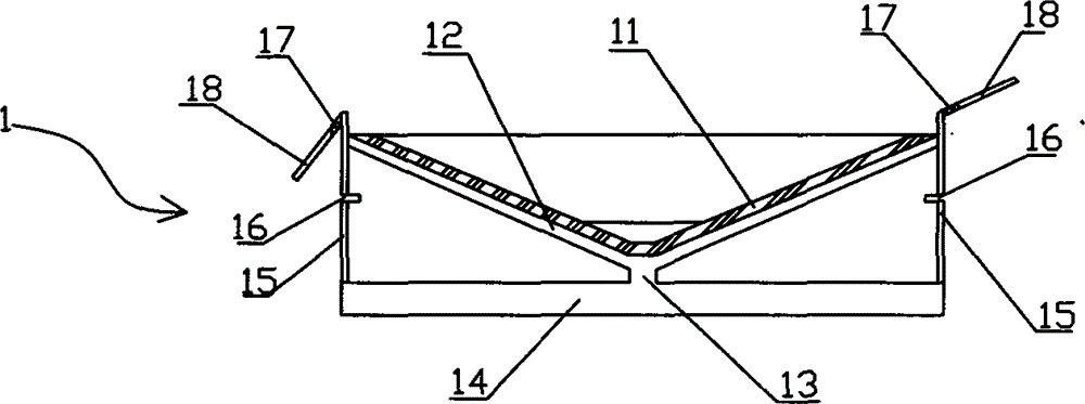
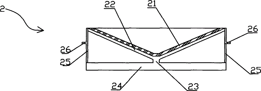
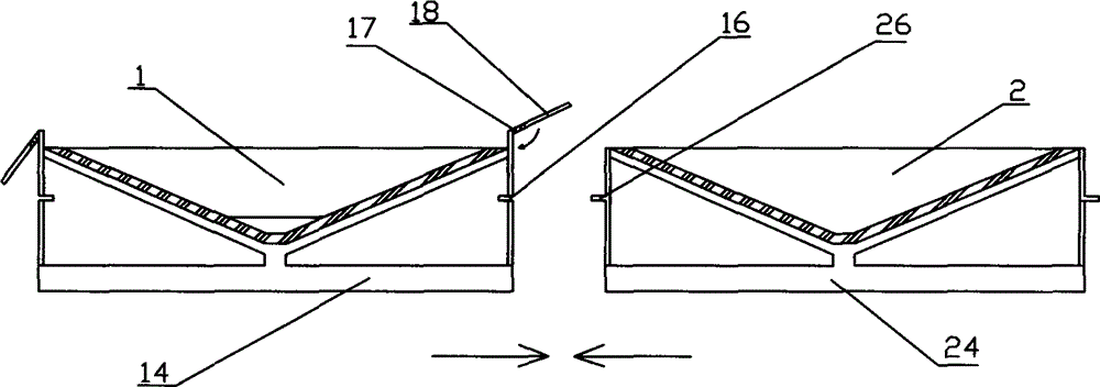
[0045] The main body of the dredging type roof drainage device described in the application of the present invention includes a plurality of drainage units laid on the roof that are spliced ​​with each other and connected as a whole. unit 1 and the lower second drainage unit 2, where, as figure 1 As shown, the top ...


PUM


Abstract

The invention provides a dredging-type roof drainage device, comprising a plurality of drainage units paved on a roof, wherein the drainage units are mutually spliced to be integrally connected; the top of each drainage unit is open, a funneled permeable layer made of a permeable material extends down inwards from the open of the top; water chutes tilting downwards along the permeable layer are arranged below the permeable layer, and are jointed below the lowest point of the permeable layer to form a water outlet; main drainage pipes connected with the water outlet are arranged below the water outlet; two adjacent drainage units are different in height, the edge of the higher drainage unit is provided with a water guide plate folded downwards and covering the joints of the two drainage units, main drainage pipes of two adjacent drainage units are mutually communicated to form a reticular drainage passageway, and the contact parts of the side walls of the two adjacent drainage units are provided with a connection device for tightly connecting the drainage units so as to realize integration of the whole drainage device, so that rainwater can be drained to a set position from the roof accordingly.

Description

technical field [0001] The application of the present invention relates to a drainage device, especially a device installed on the roof of a building for dredging and draining rainwater. Background technique [0002] At present, the structure of the roof is usually asphalt at the bottom. A leveling layer is made on the asphalt, and a waterproof layer is painted on it. The waterproof layer is covered with a protective layer. The protective layer is covered with a layer of heat insulation layer. Then cover with a layer of concrete about 10 centimeters, and the existing roof drainage mainly adopts the method of intercepting and retaining water. Water has the property of pervasiveness, so as long as there is a small damage to the waterproof layer when blocking water, it will be invaded by water, and then local water intrusion will form, and finally it will become more and more serious. The longer the building, the weaker its defense capability, and the more prone to water leaka...

Claims


Application Information

Patent Timeline
Patent Type & Authority Patents(China)
IPC IPC(8): E04D13/04E04D13/064
Inventor 韩昆
Owner 韩昆
Why Eureka
Try Eureka