Air cooling heat exchange device for heat pipe energy transporting system

A technology of heat exchange device and heat pipe condenser, which is applied in the field of energy-saving and environmentally friendly air-cooled heat exchange devices, high-efficiency, air-cooled heat exchange devices, can solve the problems of low heat exchange efficiency and air temperature rise, and achieve heat exchange efficiency. Improve, enhance heat exchange effect, increase the effect of ventilation

Inactive Publication Date: 2012-11-14
QINGDAO UNIV
View PDF7 Cites 5 Cited by
  • Summary
  • Abstract
  • Description
  • Claims
  • Application Information

AI Technical Summary

Problems solved by technology

[0003] The purpose of the present invention is to overcome the shortcomings existing in the air-cooled heat exchange device used in the existing heat pipe energy transport system, seek to design and propose a high-efficiency air-cooled heat exchange device suitable for the heat pipe

Method used


Image

  • Air cooling heat exchange device for heat pipe energy transporting system
  • Air cooling heat exchange device for heat pipe energy transporting system

Examples


Embodiment 1

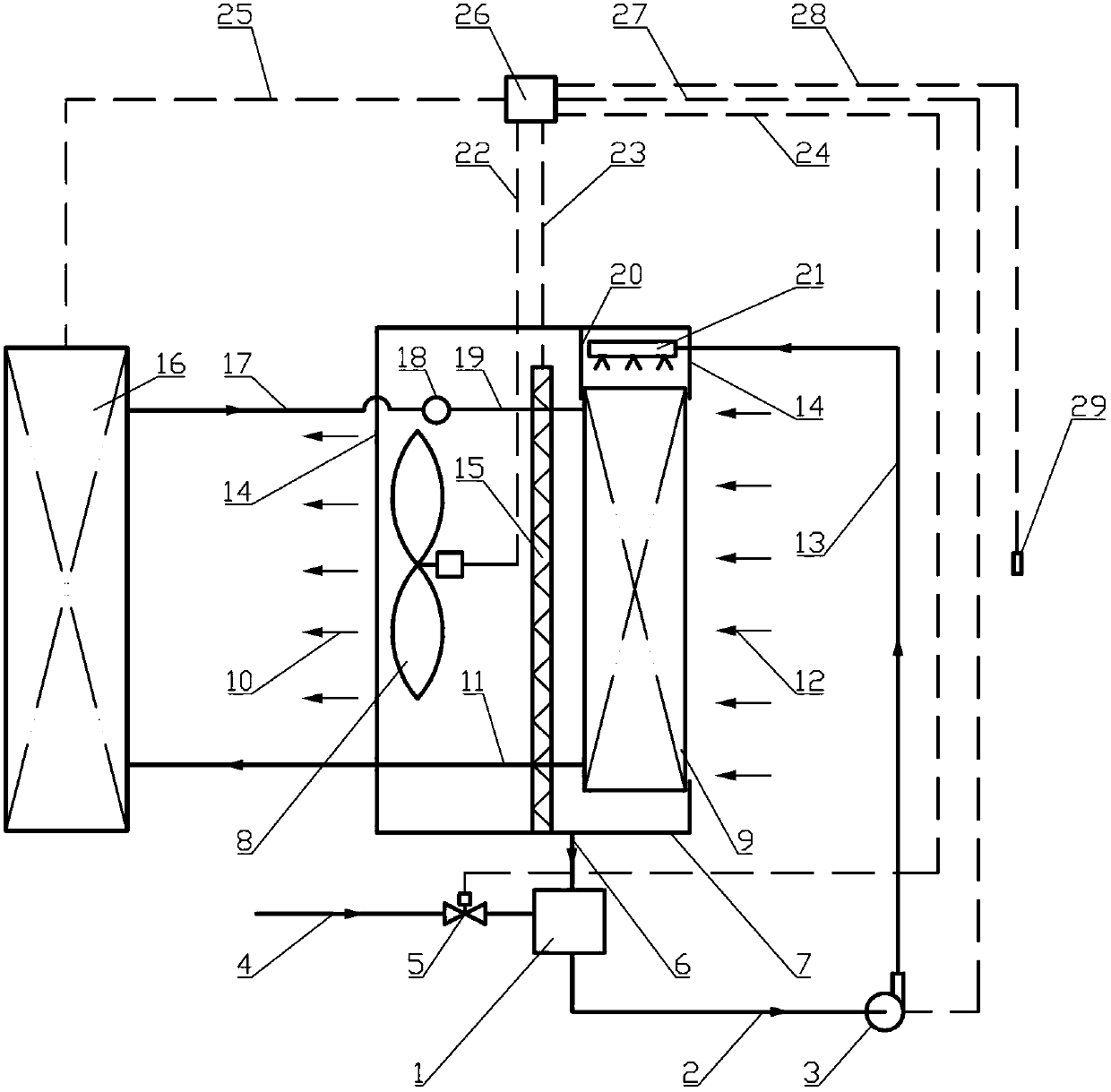
[0019] The structural principle and working flow schematic diagram of the first high-efficiency air-cooled heat exchange device suitable for the heat pipe energy transport system involved in this embodiment is as follows: figure 1 As shown, it includes a supplementary water supply and control subsystem composed of a water tank 1, a water supply pipe 4 and a water control valve 5; Plate 15, water tray 7 and water return pipe 6 are connected to form a circulating water supply and distribution subsystem; heat pipe evaporator combination 16, heat pipe gaseous (gas-liquid two-phase flow) working medium feeding pipe 17, heat pipe gaseous (gas-liquid two-phase flow) phase flow) working medium distributor 18, the heat pipe gaseous (gas-liquid two-phase flow) working medium equalizing pipe 19, the heat pipe condenser 9 and the heat pipe liquid working medium return pipe 11 are connected to form the heat pipe body subsystem; the air inlet 12, the heat pipe Condenser 9, outer sealing she...

Embodiment 2

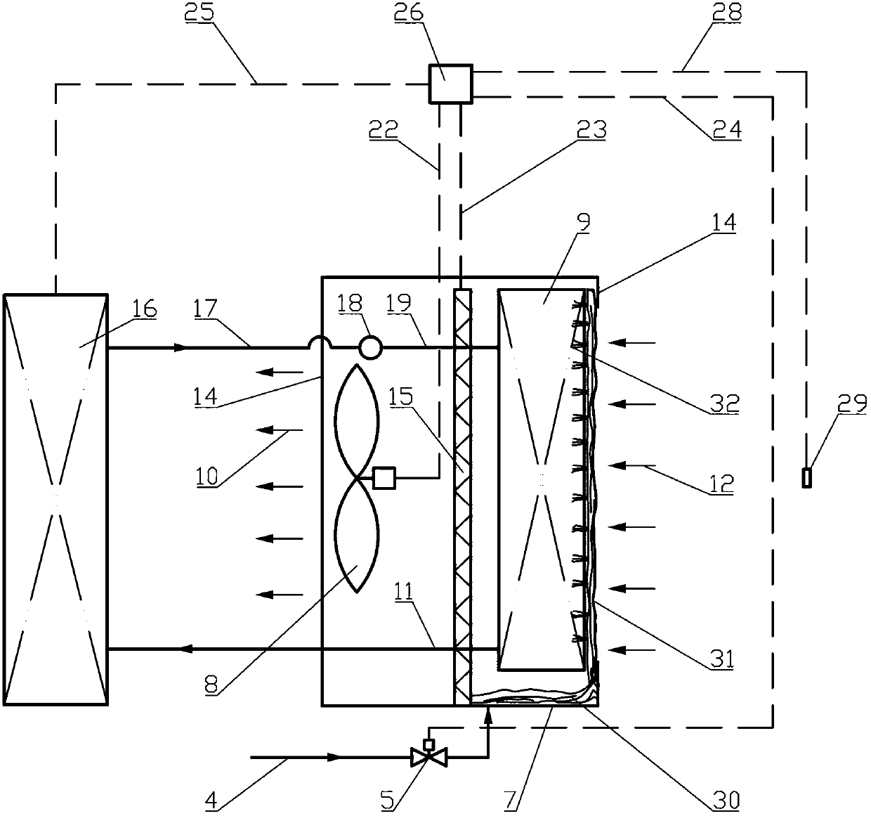
[0021] The structural principle and working flow diagram of the second air-cooled heat exchange device involved in this embodiment are as follows: figure 2 As shown, it includes a supplementary water supply and control subsystem composed of a water receiving tray 7, a water supply pipe 4 and a water control valve 5; Circulating water supply and distribution subsystem formed by connecting water tray 7; heat pipe evaporator and other combinations 16, heat pipe gaseous (gas-liquid two-phase flow) working medium feeding pipe 17, heat pipe gaseous (gas-liquid two-phase flow) working medium distribution 18, the heat pipe gaseous (gas-liquid two-phase flow) working medium equalizing pipe 19, the heat pipe condenser 9 and the heat pipe liquid working medium return pipe 11 are connected to form the heat pipe body subsystem; the air inlet 12, the heat pipe condenser 9, and the outer sealing shell 14. The air flow and treatment subsystem composed of the water baffle 15, the fan 8 and th...


PUM


Abstract

The invention belongs to the technical field of energy transporting devices and relates to an air cooling heat exchange device for a heat pipe energy transporting system. A make-up water supplying and controlling subsystem enables water level in a water tank to be constant. A circulating water circulation and distribution subsystem enables circulating water to be circulated normally. A heat pipe working medium in a heat pipe body subsystem transfers heat to the air to be cooled and then returns to an original heat pipe system to achieve deep cooling. An air flowing and processing subsystem achieved even transformation cooling of inlet air through a heat pipe condenser through driving force under the driving force of a fan, recovers water drops through a water blocking plate and discharges high-humidity air out. A central controller obtains outdoor temperature and humidity numerical values through an outer environment temperature and humidity signal line and adopts different cooling modes to perform control according to control programs of the central controller. Five subsystems are organically matched in a water, electricity and gas mode to form an air cooling heat exchange system so as to achieve the air cooling heat exchange effect. The air cooling heat exchange device is simple in structure, high in heat exchange efficiency, energy-source-saving, small in thermal pollution and wide in application range.

Description

Technical field: [0001] The invention belongs to the technical field of energy transport equipment, and relates to an air-cooled heat exchange device with high efficiency, energy saving and environmental protection, in particular to an air-cooled heat exchange device for a heat pipe energy transport system. Background technique: [0002] At present, many industrial and agricultural production processes involve the process of discharging waste heat or waste heat into the ambient air, such as the cooling of lubricating oil for large equipment, various chemical production processes with excess heat, communication base station rooms, various power cabinets and control cabinets Due to the existence of the internal heat source, it is necessary to transfer the heat generated by the internal heat source to the external environment, that is, to transport heat energy from one area to another. Heat pipe technology realizes energy transport in the form of "latent heat", which is an ener...

Claims


Application Information

Patent Timeline
IPC IPC(8): F28D15/02F28D15/06F28D5/02F28D1/00
Inventor 田小亮刘瑞璟孙晖王兆俊王宗伟任杰
Owner QINGDAO UNIV
Why Eureka
Try Eureka