
Color filter and manufacturing method thereof

A color filter and color filter technology, applied in the field of optical filters, can solve problems such as color distortion, color confusion, and interactive overlapping, and achieve the effects of avoiding inaccurate alignment, saving manufacturing costs, and increasing aperture ratio

Inactive Publication Date: 2012-11-14
BOE TECH GRP CO LTD
View PDF7 Cites 3 Cited by
  • Summary
  • Abstract
  • Description
  • Claims
  • Application Information

AI Technical Summary

Problems solved by technology

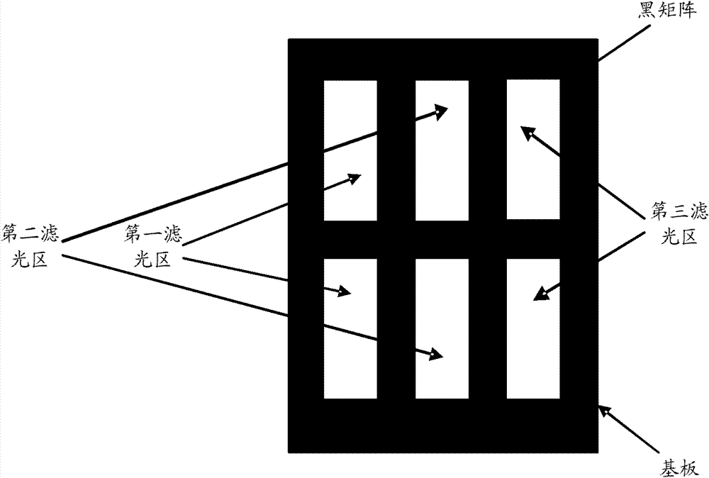
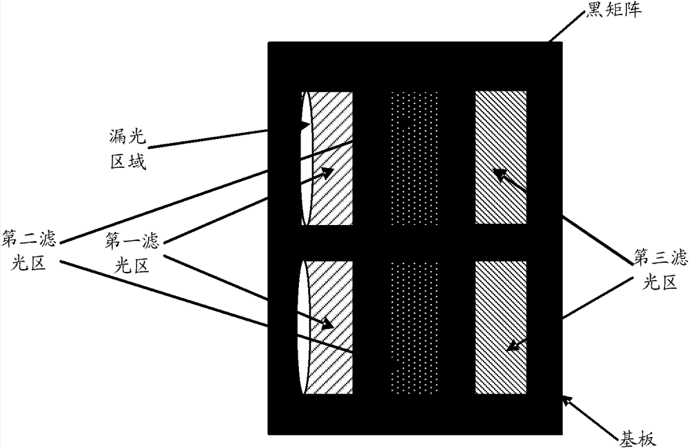
However, there are unavoidable alignment errors in the actual manufacturing process, which makes the actual position of the color filter pattern deviate from the ideal position, which leads to the inability of the color filter area to fill the opening
like Figure 1B As shown, this will cause the color filter to leak light due to the poor effect of the black matrix; in addition, the alignment error may also cause two adjacent color filter regions to overlap (cross-talk). , resulting in color mixing, resulting in color confusion, color distortion and other consequences
Moreover, the degree of overlap between the color filter area and the black matrix will affect the surface flatness of the color filter pattern, and then the backlight or ambient light will be deflected after passing through the color filter pattern. The optical quality of the filter is greatly reduced

Method used


Image

  • Color filter and manufacturing method thereof
  • Color filter and manufacturing method thereof
  • Color filter and manufacturing method thereof

Examples


Embodiment Construction

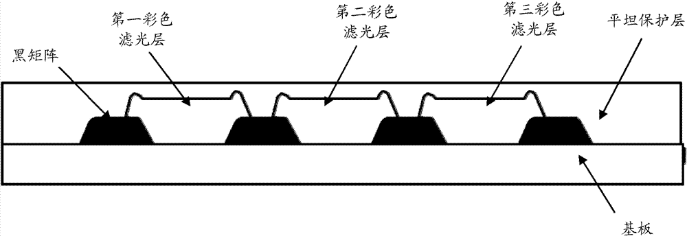
[0033] In the present invention, firstly, the ink-repellent treatment can be carried out on the substrate, and the larger contact angle formed between the ink-repellent surface and the photoresist can be used to make the color filter region form a shape with a wide top surface and a narrow bottom surface, so as to be compatible with the black The matrices are closely connected; then, the black matrix is ​​made by the method of back exposure. The above operation method increases the aperture ratio of the color filter while reducing a mask plate, which can ensure the flatness of the color filter; moreover, it can avoid light leakage and color mixing, and then obtain low cost and high flatness. , Optical quality color filter structure.

[0034] Specifically, firstly, an ink-repellent layer can be coated on the substrate, and then three color filter regions of R, G, and B can be sequentially formed on the substrate by using a front-side coating, exposure and development method. D...


PUM


Abstract

The invention discloses a color filter and a manufacturing method thereof, wherein color filter areas are arranged on a substrate at intervals in order, the area of the bottom surface of each color filter area which contacts with the substrate is caused to be less than that of the contacted top surface which does not contact with the substrate, and grid-shaped openings are formed between the adjacent color filter areas respectively; and black matrixes which are closely connected with the adjacent color filter areas are formed in the openings respectively by a back-face exposure method. The surface evenness of the color filter is effectively improved; and moreover, the finally-formed black matrixes are closely connected with the adjacent color filter areas, so that the phenomena of light leak and color mixing caused by the imprecise alignment of photo masks during exposure are prevented.

Description

technical field [0001] The invention relates to optical filter technology, in particular to a color filter (color filter) and a manufacturing method thereof. Background technique [0002] At present, the more commonly used methods of making color filters include: dyeing method, pigment dispersion method, printing method, electroplating method, etc. Based on production cost and quality considerations, the color filter produced by the pigment dispersion method has high precision, better optical rotation resistance and heat resistance, and has become the main production method of thin-film transistor (TFT) type color filter. [0003] Specifically, the pigment dispersion method mainly adopts four photolithography processes to respectively form a black matrix (black matrix) and red (R), green (G), and blue (B) filter regions. Generally speaking, the black matrix can avoid color mixing between color filter patterns of different colors. Therefore, the black matrix must be arranged...

Claims


Application Information

Patent Timeline
Patent Type & Authority Applications(China)
IPC IPC(8): G02B5/20G03F7/00
Inventor 齐永莲杨久霞薛建设
Owner BOE TECH GRP CO LTD
Learn More