High beam quality signal light fiber beam combiner and manufacture method thereof

A fiber combiner and quality signal technology, applied in the field of lasers, can solve problems such as deterioration of beam quality, degradation of beam quality, and difficulty in implementation

Inactive Publication Date: 2012-11-14
WUXI RES INST OF APPLIED TECH TSINGHUA UNIV
View PDF9 Cites 21 Cited by
  • Summary
  • Abstract
  • Description
  • Claims
  • Application Information

AI Technical Summary

Problems solved by technology

Adaptive mirrors can transmit lasers from different paths to the same position to generate superposition of power, but require extremely high orientation accuracy, making it difficult to achieve
However, the fused tapered fiber coupler destroys the core structure of the signal fiber and deteriorates the quality of the laser beam after beam combining
For example, the Chinese patent, signal optical beam combiner and its manufacturing method (publication number CN101866032A), combines the butt ends of multiple input fibers into a bundle through high-temperature fusion tapering and fus...

Method used


Image

  • High beam quality signal light fiber beam combiner and manufacture method thereof
  • High beam quality signal light fiber beam combiner and manufacture method thereof
  • High beam quality signal light fiber beam combiner and manufacture method thereof

Examples


Embodiment 1

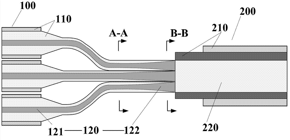
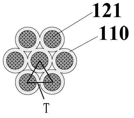
[0063] Such as Figures 3A to 3C As shown, in this example, the high-beam quality signal optical fiber bundler combines 7 signal fibers, and a circular double-clad signal fiber 100 with a core / inner cladding diameter of 20 / 130um is close to the output fiber. The coating layer (including the outer cladding) of a section of the signal optical fiber 100 at the fusion point is removed by 4 cm, exposing the inner cladding. Adopt HF to chemically corrode a section of signal optical fiber 100 of the decoated layer of double-clad signal optical fiber 100 to reduce its diameter to 30um, and then insert the processed seven signal optical fibers 100 with a length of 4cm and an inner diameter / outer diameter of 4 cm. 90 / 150um low-refractive-index quartz tube 300, and then heat the quartz tube with a hydrogen-oxygen flame to weakly fuse the 7 signal optical fibers 100 and the quartz tube with each other, and finally cut it off from the center, with a size of 90 / 150um double-clad The layer ...

Embodiment 2

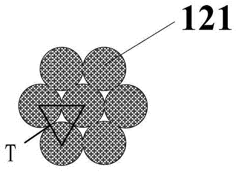
[0065] Such as Figures 4A-4C As shown, in this example, the high-beam-quality signal optical fiber combiner is a place where three circular double-clad signal fibers 100 with core / inner cladding diameters of 10 / 125um are placed close to the fusion splicing point with the output fiber The coating (including the outer cladding) of a section of the signal optical fiber 100 is removed by 4 cm to expose the inner cladding, and the section of the signal optical fiber 100 with the decoating layer of the double-clad signal optical fiber 100 is chemically etched by HF to reduce its diameter to 20um , and then arrange the processed three signal optical fibers 100 into a zigzag optical fiber bundle, such as Figure 4B and 4C structure shown. Then heat the arranged optical fiber bundle with a hydrogen-oxygen flame to make the three signal optical fibers 100 weakly fuse with each other, and finally cut it off from the center of the heating zone, and weld it with a double-clad output fib...


PUM


Abstract

The invention provides a high beam quality signal light fiber beam combiner and a manufacture method thereof. The beam combiner comprises at least one signal optical fiber which forms one group and output optical fibers. The signal optical fiber comprises an optical fiber cladding and a fiber core, the fiber core comprises a fiber core body and a fiber core through connection portion, one end of the fiber core through connection portion is connected with one end of the fiber core body, and the cross sectional area of the fiber core through connection portion gradually increases from one end to the other end to enable the fiber core through connection portion to approximately be conical, the refractive index of the fiber core through connection portion gradually reduces from one end to the other end, and a V parameter is invariant. One ends of the output optical fibers are connected with the other end of the fiber core through connection portion of the group of the signal optical fiber. The high beam quality signal light fiber beam combiner adopts the fiber core through connection portion to enable the duty ratio of signal light at a welding position of a plurality of optical fibers and the output optical fibers to achieve 1, enables combined output laser angle relative packing ratio (angles of 1) to be greatly reduced, and effectively promotes output laser beam quality.

Description

technical field [0001] The invention relates to the technical field of lasers. A high beam quality signal optical fiber combiner and a manufacturing method of the high beam quality signal optical fiber combiner are specially designed. Background technique [0002] At present, IPG reports that the continuous output power of single-mode fiber laser has reached 10kW. However, limited by nonlinear effects such as stimulated Brillouin scattering and stimulated Raman scattering, as well as thermal effects and high power density damage to the fiber, it is extremely difficult to further increase the laser power of a single gain fiber. In order to obtain higher power fiber laser output, coherent combining and incoherent combining methods have been proposed successively. Coherent combining is to use a certain technology to lock the phases of several lasers with the same working wavelength, so that the lasers emitted by these lasers are superimposed in the far field. However, cohere...

Claims


Application Information

Patent Timeline
IPC IPC(8): G02B6/24G02B6/245G02B6/255
Inventor 闫平巩马理肖起榕郝金坪张海涛
Owner WUXI RES INST OF APPLIED TECH TSINGHUA UNIV
Why Eureka
Try Eureka