Check patentability & draft patents in minutes with Patsnap Eureka AI!

Reflecting type array waveguide grating based on multiple-mode interferometer reflector

An arrayed waveguide grating and multi-mode interference technology, which is applied in the coupling of optical waveguides, light guides, optics, etc., can solve problems that are not suitable for industrial production, high requirements for equipment and operators, and improve efficiency and yield, reduce area, The effect of reducing length

Inactive Publication Date: 2012-11-14
SOUTH CHINA UNIV OF TECH
View PDF4 Cites 13 Cited by
  • Summary
  • Abstract
  • Description
  • Claims
  • Application Information

AI Technical Summary

Problems solved by technology

The manufacturing precision of this structure is very high, and the requirements for equipment and operators are high, so it is not suitable for industrial production

Method used


Image

  • Reflecting type array waveguide grating based on multiple-mode interferometer reflector
  • Reflecting type array waveguide grating based on multiple-mode interferometer reflector
  • Reflecting type array waveguide grating based on multiple-mode interferometer reflector

Examples


Embodiment Construction

[0031] The specific implementation of the present invention will be further described below in conjunction with the accompanying drawings, but the implementation and protection scope of the present invention are not limited thereto.

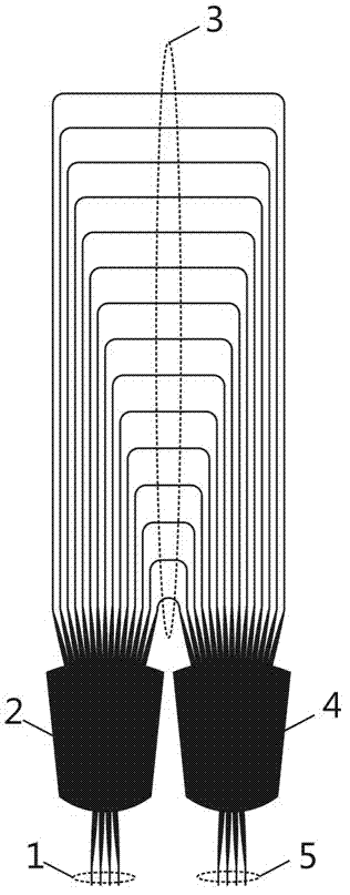
[0032] Such as figure 2 , is a schematic structural diagram of a reflective arrayed waveguide grating based on a multimode interferometer mirror, including an input waveguide 1 , a coupler 2 , an arrayed waveguide 3 , a mirror 6 and an output waveguide 5 . The input waveguide 1 and the output waveguide 5 are located on the same side of the coupler 2, and the arrayed waveguide 3 is located on the other side of the coupler 2; the arrayed waveguide 3 is composed of a plurality of silicon nanowire waveguides, and one end of each silicon nanowire waveguide It is connected with the coupler 2, and the other end is connected with a reflector 6.

[0033] The length difference Δ of adjacent silicon nanowire waveguides L Can be expressed as:

[0034] ...


PUM


Abstract

The invention provides a reflecting type array waveguide grating based on a multiple-mode interferometer reflector. The reflecting type array waveguide grating comprises an input waveguide, a coupler, an array waveguide, a reflector and an output waveguide, wherein the input waveguide and the output waveguide are arranged on the same side of the coupler, and the array waveguide is arranged on the other side of the coupler. The array waveguide is composed of a plurality of nanometer wire waveguides, one end of each nanometer wire waveguide is connected with the coupler, the other end of each nanometer wire waveguide is connected with the reflector, and the reflector is a plane wave guide structure formed by a multi-mode interferometer and an annular waveguide. The reflecting type array waveguide grating is totally based on the plane light waveguide technology, the waveguide narrowest in width is a single-mode waveguide, and the requirements for manufacture accuracy of the waveguide is totally in accordance with that of the ordinary nanometer wire array waveguide grating. By adopting the reflector based on the multi-mode interferometer, the reflector is not sensitive in errors of the wavelength and the manufacture process. The array waveguide is flexible in structural design and can be distributed randomly according to requirements.

Description

technical field [0001] The invention relates to the field of planar optical waveguide integrated devices, in particular to a reflective arrayed waveguide grating. Background technique [0002] Based on planar optical waveguide technology, arrayed waveguide gratings have the advantages of small wavelength interval, large number of channels, uniform channel loss, small size, easy integration, and convenient mass production. It is considered to be the most suitable for large-capacity dense wavelength division multiplexing systems. key components. The miniaturization of arrayed waveguide gratings has been an important research topic. [0003] At present, the most widely used arrayed waveguide grating is based on silicon dioxide material system, with a typical size of 10cm 2 Magnitude. With the development of large-scale integrated devices, the miniaturization of devices is an inevitable trend. Increasing the refractive index difference between the waveguide core and cladding...

Claims


Application Information

Patent Timeline
IPC IPC(8): G02B6/293G02B6/26
Inventor 黄华茂胡海英
Owner SOUTH CHINA UNIV OF TECH
Features
  • R&D
  • Intellectual Property
  • Life Sciences
  • Materials
  • Tech Scout
  • Unparalleled Data Quality
  • Higher Quality Content
  • 60% Fewer Hallucinations
Learn More