Producing nanoparticle solutions based on pulsed laser ablation

A nanoparticle and pulse technology, applied in the field of preparing thin-film solar cells, can solve problems such as improper composition and impurities

Inactive Publication Date: 2012-11-14
IMRA AMERICA
View PDF5 Cites 15 Cited by
  • Summary
  • Abstract
  • Description
  • Claims
  • Application Information

AI Technical Summary

Problems solved by technology

Incomplete reduction will lead not only to impurity phases but also to improper composition

Method used


Image

  • Producing nanoparticle solutions based on pulsed laser ablation
  • Producing nanoparticle solutions based on pulsed laser ablation
  • Producing nanoparticle solutions based on pulsed laser ablation

Examples


Embodiment Construction

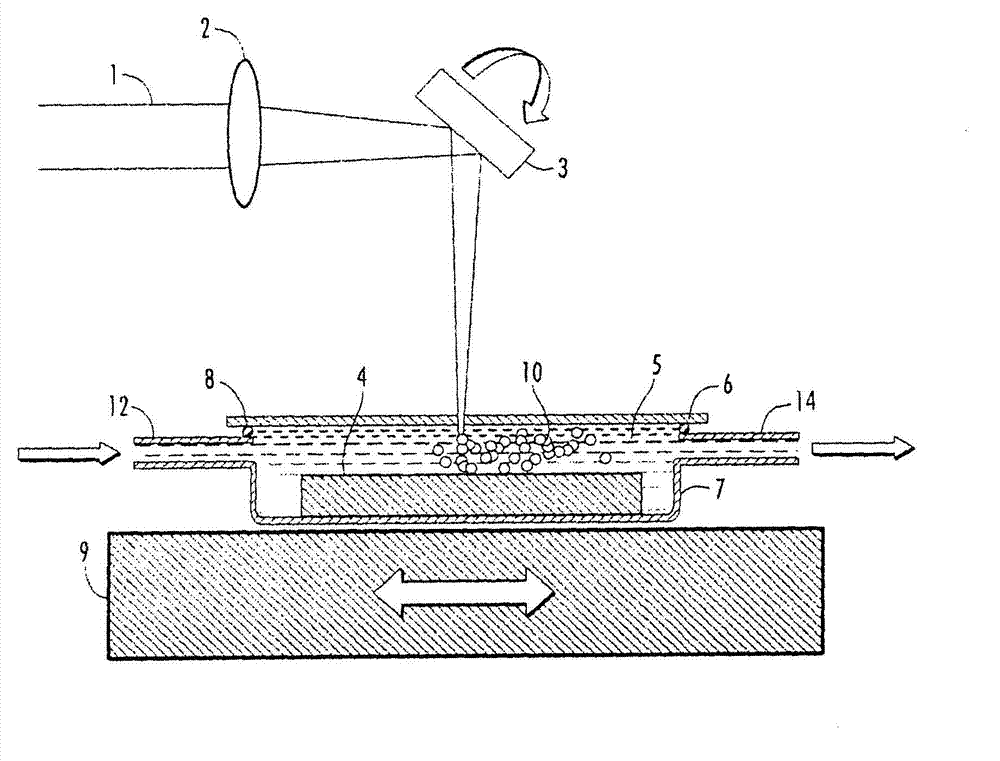
[0021] figure 1 Schematic illustration of a laser-based system for the preparation of nanoparticles of complex compounds in liquids according to the invention. In one embodiment, a laser beam 1 is received from a pulsed laser source (not shown) and focused with a lens 2 . The source of the laser beam 1 can be a seed laser or any other laser source known in the art as long as it has the pulse duration, repetition rate and power level as described below. The focused laser beam 1 is then directed from the lens 2 to a guide mechanism 3 for controlling the movement of the laser beam 1 . The guiding mechanism 3 may be any guiding mechanism known in the art, including for example piezo-mirrors, acousto-optic deflectors, rotating polygons, vibrating mirrors and prisms. The guiding mechanism 3 is preferably a vibrating mirror 3 capable of controlling and rapidly moving the laser beam 1 . The guide 3 guides the laser beam 1 towards the target 4 . The target 4 is made of the desired ...


PUM

PropertyMeasurementUnit
wavelengthaaaaaaaaaa
band gapaaaaaaaaaa

Abstract

A method of producing nanoparticles of solar light absorbing compound materials based on pulsed laser ablation is disclosed. The method uses irradiation of a target material of solar light absorbing compound material with a pulsed laser beam having a pulse duration of from 10 femtoseconds to 500 picoseconds to ablate the target thereby producing nanoparticles of the target The nanoparticles are collected and a solution of the nanoparticles is applied to a substrate to produce a thin film solar cell. The method preserves the composition and structural crystalline phase of the starting target. The method is a much lower cost fabrication method for thin film solar cells.

Description

[0001] related application [0002] This application claims the benefit of US Provisional Application Serial No. 61 / 302995, filed February 10, 2010. [0003] Statement Regarding Federally Funded Research [0004] none. field of invention [0005] The present invention relates to the preparation of thin film solar cells, and more particularly to the use of pulsed laser ablation of source materials in liquids to prepare nanoparticle solutions for use in the manufacture of thin film solar cells. Background of the invention [0006] Thin-film solar cells consume significantly less source material and are therefore less expensive to manufacture than monocrystalline solar cells. In current thin-film solar cell fabrication, the light-absorbing layer, which is the most critical layer, is usually fabricated using vacuum methods such as thermal evaporation, chemical vapor deposition, and sputtering. Precise control of film deposition is required for compounds consisting of: group I...

Claims


Application Information

Patent Timeline
Patent Type & Authority Applications(China)
IPC IPC(8): B32B9/04B82B3/00B22F1/0545
CPCH01L31/035281B22F9/04B23K26/365B22F2998/00Y02E10/543B82Y40/00B22F1/0022H01L31/0296Y02E10/541H01L31/03923H01L31/0322B22F2999/00H01L31/1828H01L31/03925B82B1/001B23K26/361Y02P70/50B22F1/0545B22F2202/11B22F1/054B22F1/056
Inventor 刘冰车勇
Owner IMRA AMERICA
Why Eureka
Try Eureka