Condenser for vehicle and air conditioning system for vehicle

An air-conditioning system and condenser technology, applied in the direction of air-conditioning systems, evaporators/condensers, vehicle components, etc., can solve the problems of increased power consumption, increased coolant temperature at the outlet of the condenser, increased cost and weight, etc., to achieve Effect of increased secondary cooling area and temperature, improved overall cooling performance, improved overall durability

Active Publication Date: 2012-11-21
HYUNDAI MOTOR CO LTD +1
View PDF12 Cites 15 Cited by
  • Summary
  • Abstract
  • Description
  • Claims
  • Application Information

AI Technical Summary

Problems solved by technology

Therefore, the cost and weight will increase, and the connection between the receiver-dryer and the condenser will be complicated
[0012] When the coolant is cooled by water in a conventional air conditioning system, the coolant cooled by the outside air exchanges heat with the coolant of the condenser, thereby increasing the temperature of the coolant at the outlet of the condenser, so there is a problem of increased power consumption
[0013] Also, when the secondary cooling area is increased to improve the cooling performance in the conventional air conditioning system by increasing the heat exchange amount of the coolant, the superheating process is increased above the base temperature, and the internal temperature of the compressor is increased, so the electric compressor may Damaged by the heat and at the same time there is a problem of unvaporized liquid refrigerant flowing in it and the compressor is damaged
[0014] Also, when the evaporator enthalpy is increased by increasing the secondary cooling area in the conventional air conditioning system, the cooling performance is improved, but the suction amount of the compressor is increased due to the increase in the specific volume according to the increase in the inlet / outlet coolant temperature of the compressor And lower, the evaporation capacity of the evaporator is reduced, so there is a limitation in improving its cooling performance

Method used


Image

  • Condenser for vehicle and air conditioning system for vehicle
  • Condenser for vehicle and air conditioning system for vehicle
  • Condenser for vehicle and air conditioning system for vehicle

Examples


Embodiment Construction

[0056] Reference will now be made in detail to various embodiments of the invention, examples of which are illustrated in the accompanying drawings and described below. While the invention will be described in conjunction with exemplary embodiments, it will be understood that present description is not intended to limit the invention to those exemplary embodiments. On the contrary, the invention is intended to cover not only the exemplary embodiments, but also various alternatives, modifications, equivalents and other embodiments, which may be included within the spirit and scope of the invention as defined by the appended claims .

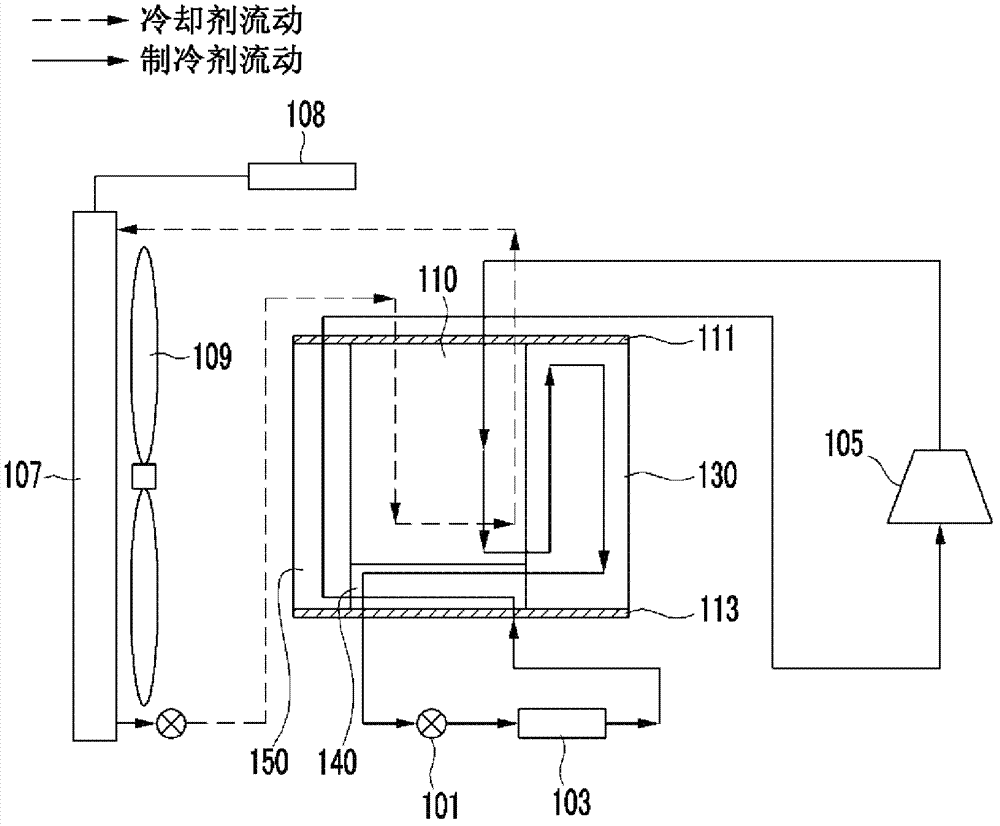
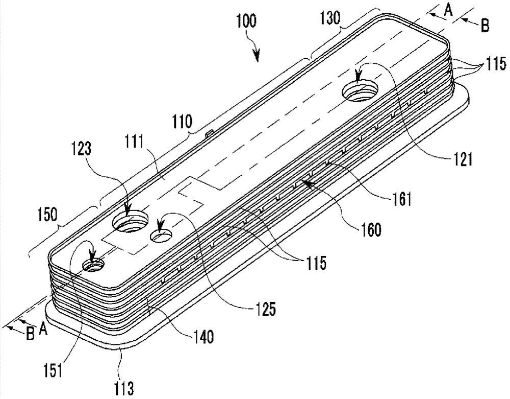
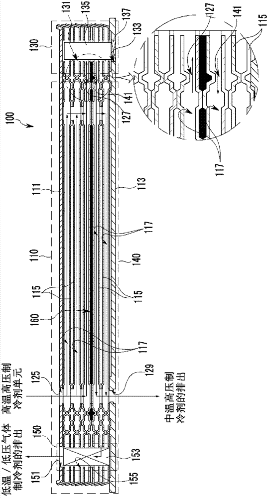
[0057] figure 1 is a block diagram of a vehicle air conditioning system applied to a condenser for a vehicle according to an exemplary embodiment of the present invention, figure 2 is a perspective view of a condenser for a vehicle according to an exemplary embodiment of the present invention, image 3 for along figure 2 A cross-sectional v...


PUM


Abstract

A condenser may include a main radiating portion including a plurality that is formed by laminating a plurality of plates, a receiver drier portion integrally formed at one side end of the main radiating portion, a supercooling radiator that is integrally formed at a lower portion of the main radiating portion, and an accumulator portion integrally formed with the main radiating portion and the other end portion of the supercooling radiator. An air conditioning system may include an expansion valve, an evaporator, and an electrically driven compressor, a water cooler condenser, and a heat exchanger, wherein a liquid state refrigerant of a middle temperature and high pressure passing the water cooler condenser exchanges heat with a low temperature / pressure refrigerant passing the evaporator in the heat exchanger.

Description

[0001] Cross References to Related Applications [0002] This application claims priority and benefit from Korean Patent Applications No. 10-2011-0048077 and No. 10-2011-0084194 filed on May 20, 2011 and August 23, 2011, respectively, the entire contents of which Incorporated herein for all purposes by this reference. technical field [0003] The present invention relates to a condenser for a vehicle and an air conditioning system for a vehicle. More particularly, the present invention relates to a condenser for a vehicle that uses a coolant to condense a refrigerant, and an air conditioning system for a vehicle that prevents thermal aging of a compressor to improve overall cooling performance. Background technique [0004] Generally, an air conditioner for a vehicle maintains an appropriate cabin temperature regardless of the ambient temperature, and realizes a comfortable indoor environment. [0005] This air conditioner includes a compressor that compresses refrigerant,...

Claims


Application Information

Patent Timeline
Patent Type & Authority Applications(China)
IPC IPC(8): F25B39/04F24F1/00
CPCF25B39/04F28D9/005F24F1/00B60H1/32B60H1/00F28D2021/0084F25B40/00F25B43/003F25B2339/047B60H1/00335B60H1/3227Y02T10/88
Inventor 金载然李淳钟赵完济朴万熙金允晟
Owner HYUNDAI MOTOR CO LTD
Why Eureka
Try Eureka