Chest diagnostic support information generation system

A technology for diagnosis assistance and information generation, which is applied in the fields of diagnosis, informatics, medical informatics, etc., and can solve the problems of inability to calculate feature quantities, processing time, and difficulty in obtaining accuracy.

Active Publication Date: 2012-11-28
KONICA MINOLTA MEDICAL & GRAPHICS INC
View PDF8 Cites 20 Cited by
  • Summary
  • Abstract
  • Description
  • Claims
  • Application Information

AI Technical Summary

Problems solved by technology

[0006] In the above-mentioned Japanese Patent Laid-Open No. 2009-136573, in order to perform high-precision analysis, it is necessary to exclude the positional movement of the blood vessel region, in other words, it is necessary to stop breathing, and it is impossible to calculate the characteristic quantity related to ventilation.
In International Publication No. 2009 / 090894, although the two feature quantities related to ventilation and blood flow can be calculated through one shot data, in order to obtain high-precision analysis results, high-precision analysis of each small area is required. Because of deformation processing, processing time is required. In addition, since the two feature quantities are calculated with the same processing algorithm (inter-frame difference signal value), it is difficult to obtain the same accuracy as the feature quantity related to ventilation for the feature quantity related to blood flow. shortcoming

Method used


Image

  • Chest diagnostic support information generation system
  • Chest diagnostic support information generation system
  • Chest diagnostic support information generation system

Examples


no. 1 Embodiment approach

[0063] [Configuration of Chest Diagnosis Supporting Information Generation System 100 ]

[0064] First, the configuration will be described.

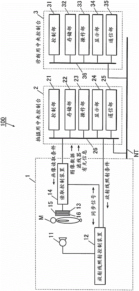
[0065] figure 1 The overall structure of the chest diagnostic support information generating system 100 in the first embodiment is shown in .

[0066] Such as figure 1 As shown, the chest diagnosis auxiliary information generating system 100 is constituted as follows: the photographing device 1 and the central console 2 for photographing are connected via a communication cable or the like, and the central console 2 for photographing and the central console 3 for diagnosis are connected via a LAN (Local Area Network). : LAN) and other communication network NT connections. Each device constituting the breast diagnostic support information generating system 100 is based on the DICOM (Digital Image and Communications in Medicine: Digital Image and Communications in Medicine) standard, and communication between the devices is performed i...

no. 2 Embodiment approach

[0224] Next, a second embodiment of the present invention will be described.

[0225] In the second embodiment, a case will be described in which the present invention is applied to a mobile chest diagnostic support information generation system 70 for a patient who has difficulty moving. Such as Figure 24 As shown, the mobile chest diagnosis auxiliary information generation system 70 is a kind of system 70 that is brought into the sick room Rc by each patrol car 71, and inserted into the FPD box 72 between the body of the subject H lying on the bed B and the bed B, etc. A system for generating diagnostic support information by irradiating radiation from a portable radiation source 52P and performing imaging in a state where the radioactive radiation is in a low state.

[0226] Such as Figure 24 As shown, the mobile chest diagnosis auxiliary information generating system 70 is: the portable radiation source 52P and the radiation generating device 57 are installed in the pa...


PUM


Abstract

The present invention relates to a chest diagnostic support information generation system capable of supplying accurate diagnostic support information relating to each of the breathing and the blood flow by one time of motion imaging. According to the chest diagnostic support information generation system (100), a control section (31) of a console for diagnosis (3), for a plurality of frame images obtained by motion imaging in radiography equipment (1), corresponds a pixel or a block with each other which represents signal values which a detection element of the same position in a radiation detector (13) among the plurality of image frames outputs, generates the diagnostic support information relating to breathing of the subject based on a difference value of signal values of the pixel or the block corresponded with each other between neighboring frame images in time, generates an output signal wave form which represents a temporal change of signal values of the pixel or the block corresponded with each other, and generates the diagnostic support information relating to blood flow of the subject based on the generated output signal wave form.

Description

technical field [0001] The invention relates to a system for generating auxiliary information for chest diagnosis. Background technique [0002] In contrast to conventional still image imaging and diagnosis of radiation (X-ray) using films / screens and luminous phosphor panels, imaging of diagnostic target sites is performed using semiconductor image sensors such as FPDs (flat panel detectors: Flat Panel Detectors) dynamic images and applied to diagnostic attempts. Specifically, by utilizing the quickness of the responsiveness of reading and erasing the image data of the semiconductor image sensor, combined with the timing of the reading and erasing of the semiconductor image sensor, pulse-shaped radiation is continuously irradiated from the radiation source within 1 second. A plurality of photographs are performed to photograph the dynamics of the part to be diagnosed. By sequentially displaying a series of multiple images obtained by imaging, the doctor can recognize a se...

Claims


Application Information

Patent Timeline
Patent Type & Authority Applications(China)
IPC IPC(8): A61B6/02G06T7/00
CPCA61B6/463G06T2207/10016A61B6/486G06T2207/10116A61B6/542G06T7/0016A61B6/4405A61B6/507A61B6/5205A61B6/5217A61B6/5235A61B6/468G06T2207/30061A61B6/5258A61B6/4291G16H50/30
Inventor 岛田哲雄村冈慎太郎野地翔
Owner KONICA MINOLTA MEDICAL & GRAPHICS INC
Why Eureka
Try Eureka