
Air compressor residual-heat utilization system and method

A technology of air compressors and heat exchange systems, which is applied in the direction of machines/engines, mechanical equipment, liquid variable capacity machinery, etc., which can solve the problems of incomplete utilization of waste heat of air compressor waste heat utilization equipment, so as to improve efficiency and application Range, the effect of extending the service life

Inactive Publication Date: 2012-11-28
CRRC QIQIHAR ROLLING CO LTD
View PDF6 Cites 20 Cited by
  • Summary
  • Abstract
  • Description
  • Claims
  • Application Information

AI Technical Summary

Problems solved by technology

[0016] The purpose of the present invention is to propose an air compressor waste heat utilization system to fully recover the waste heat of the air compressor in view of the above-mentioned problem of incomplete waste heat utilization of the existing air compressor waste heat utilization equipment

Method used


Image

  • Air compressor residual-heat utilization system and method
  • Air compressor residual-heat utilization system and method
  • Air compressor residual-heat utilization system and method

Examples


Embodiment 1

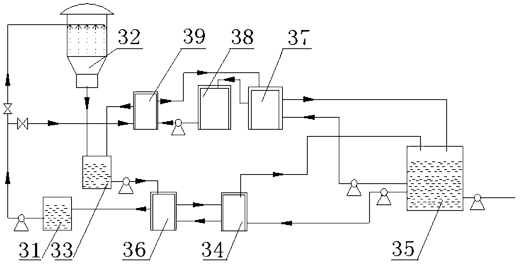
[0056] image 3 It is a structural schematic diagram of the air compressor waste heat utilization system of the present invention.

[0057] This embodiment provides an air compressor waste heat utilization system, such as image 3 As shown, it includes a water storage tank 35, a computer control system, a first heat exchange system and a second heat exchange system that respectively realize heat exchange with an air compressor;

[0058] The computer control system is electrically connected with the water storage tank, the first heat exchange system and the second heat exchange system, and is used to realize the automatic monitoring and computer management of the water storage tank, the first heat exchange system and the second heat exchange system;

[0059] The air compressor 36 is two sets of screw air compressors and four centrifugal air compressors arranged side by side; the primary cooler of the screw air compressor is provided with a water cooling device; the primary coo...

Embodiment 2

[0086] The air compressor waste heat utilization method disclosed in this embodiment takes the air compressor waste heat utilization system shown in Embodiment 1 as an example, and the air compressor is a screw air compressor and a centrifugal air compressor connected in parallel.

[0087] Before the air compressor is running, the water in the storage tank is pumped from the cold fluid inlet of the air compressor waste heat recycling device into the air compressor waste heat recycling device;

[0088] When the air compressor is running, the water in the cold water pool enters the water cooling device through the cold fluid inlet of the water cooling device, and is combined with the primary cooler of the screw air compressor and / or the primary cooler of the centrifugal air compressor and / or the centrifugal air compressor. The secondary cooler of the air compressor exchanges heat; the temperature of the water from the cold water pool increases after heat exchange and enters the h...


PUM


Abstract

The invention provides an air compressor residual-heat utilization system and method. The air compressor residual-heat utilization system comprises a water storage tank, a computer control system, and a first heat exchanging system and a second heat exchanging system which conduct heat exchange with the air compressor respectively, wherein the first heat exchanging system comprises a hot water tank, a cold water tank, a heat exchanger, an internal circulation water tank and a heat pump unit; and the second heat exchanging system comprises an air compressor residual-heat recycling device. The invention also discloses an air compressor residual-heat utilization method. The air compressor residual-heat utilization system and method overcomes a plurality of defects in the prior art, and realizes full recovery of the air compressor residual heat, and the residual-heat utilization ratio approximates 100 percent.

Description

technical field [0001] The invention relates to energy-saving technology, in particular to an air compressor waste heat utilization system and an air compressor waste heat utilization method. Background technique [0002] There are two traditional methods of heating hot water for bathing: hot water boilers and steam boilers, which can be divided into coal-fired boilers, oil-fired boilers, and gas-fired boilers according to the type of fuel. High energy consumption and serious pollution. With the development of science and technology, electric heating and solar heating have appeared in the way of heating hot water for bathing. The heating process does not produce any substances. It is a green energy, especially solar heating. It uses the resources given by nature and converts it into the heat energy needed by human beings. However, this heating method has limitations. For example, it will be affected in the case of insufficient sunlight at night and winter, and cannot provid...

Claims


Application Information

Patent Timeline
IPC IPC(8): F04B39/00
Inventor 王志国白杰刘强朱广庆仲春祥杨均悦黄本祥刘亚生崔思明刘雁景丹王凯志宋学良谢志山孙丽谭晓东
Owner CRRC QIQIHAR ROLLING CO LTD
Learn More