
Method for planning velocity of S-shaped acceleration and deceleration control for control system of numerical control equipment

A technology of acceleration and deceleration control and control system, applied in the field of numerical control, can solve the problem that motion output control cannot meet the requirements of real-time performance, and achieve the effects of avoiding jitter and shock, improving processing capacity and improving processing efficiency.

Active Publication Date: 2012-11-28
成都乐创自动化技术股份有限公司
View PDF6 Cites 30 Cited by
  • Summary
  • Abstract
  • Description
  • Claims
  • Application Information

AI Technical Summary

Problems solved by technology

However, the traditional S-shaped velocity look-ahead algorithm involves a huge amount of calculations, because it can be known from the mathematical relationship that if the motion is output with an S-shaped velocity curve, then the distance (S) will be the cube of time (t)
As a result, according to the traditional processing method, a huge amount of calculation will cause the motion output control to fail to meet the real-time requirements

Method used


Image

  • Method for planning velocity of S-shaped acceleration and deceleration control for control system of numerical control equipment
  • Method for planning velocity of S-shaped acceleration and deceleration control for control system of numerical control equipment
  • Method for planning velocity of S-shaped acceleration and deceleration control for control system of numerical control equipment

Examples


Embodiment Construction

[0046] Before describing the specific implementation manner of the present invention in detail, let us first introduce the relevant content about the S-curve technology.

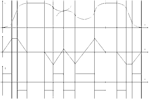
[0047] The S-shaped speed calculation method is the key technology of the current project. The algorithm goal is to control the continuity of acceleration changes to achieve a smooth transition of speed and ensure mechanical stability. Since the curves of the actual processing process are all arbitrary trajectories, the speed curve output by the controller is not a complete S-shaped curve. Generally, the speed curve output by one processing is composed of countless S-shaped speed curves. like figure 1 Shown:

[0048] from figure 1 It can be seen from the above that the distance (S) will be the cubic relationship of time (t), which is one more power than the T-type acceleration and deceleration control mode relationship. Therefore, the change of acceleration in the speed look-ahead process prevents us fro...


PUM


Abstract

The invention discloses a method for planning the velocity of S-shaped acceleration and deceleration control for a control system of numerical control equipment. A 'collimation line' concept is introduced in the method and the method comprises the following steps: setting the parameters of a vectorial line segment are set; calculating the allowed velocity Vc of a collimation line according to theinput vectorial line segment; judging whether the collimation line conditions are reached or not, if so, producing one collimation line, and adding the produced collimation line into a collimation line linked list in sequence; after the collimation line linked list is fixed, respectively calculating the maximum velocity of each collimation line according to a traversal algorithm; and completing the collimation line interpolation task through a field programmable gate array (FPGA) program, distributing the pulses of the collimation lines to all the practical movement axes of an electronic gear, and converting digital information into electrical information for controlling the movement of a motor. The method has the beneficial effects that the method is applied to S-shaped acceleration deceleration control, so that shacking and collision which are generated because a machine is very heavy can be well avoided, the operation stability of the machine is improved, and the processing efficiency is increased. The solution idea of the collimation line is introduced. The data processing amount is effectively reduced, and the data processing capability is improved.

Description

technical field [0001] The invention relates to the field of numerical control, in particular to an S-shaped acceleration and deceleration control method used in a control system of numerical control equipment. [0002] Background technique [0003] CNC machine tools can be divided into two parts: machine tools and control systems (including controllers, etc.). The machine tool is like the human body, and the control system is like the human brain and soul. The two parts form a system and are inseparable. [0004] The control system of CNC machine tools, the core part of CNC machine tools, is the brain and soul. With a good bed, there is a good body. If you want him to move, you need to give him a smart brain and a pure soul. The current control system generally consists of three parts, 1. Driver 2. Inverter 3. Engraving controller and host computer software. [0005] 1. The driver, its function is to receive the pulse signal provided by the controller to drive the ste...

Claims


Application Information

Patent Timeline
IPC IPC(8): G05B19/416
Inventor 谭平张春雷
Owner 成都乐创自动化技术股份有限公司
Learn More