Systems And Processes Of Operating Fuel Cell Systems

A fuel cell and feedstock technology, applied in fuel cells, regenerative fuel cells, fuel cell additives, etc., can solve problems such as low efficiency and insufficient heat

Inactive Publication Date: 2012-11-28
SHELL INT RES MAATSCHAPPIJ BV
View PDF3 Cites 16 Cited by
  • Summary
  • Abstract
  • Description
  • Claims
  • Application Information

AI Technical Summary

Problems solved by technology

The process is also relatively thermally inefficient in gas generation and thermal processing because the anode gas is cooled to remove water prior to entering the pressure swing adsorption unit
Also, the reformer does not convert the liquid hydrocarbon feedstock to a lower molecular weight feed for the steam reformer, and may not provide sufficient heat from the fuel cell to do so

Method used


Image

  • Systems And Processes Of Operating Fuel Cell Systems
  • Systems And Processes Of Operating Fuel Cell Systems
  • Systems And Processes Of Operating Fuel Cell Systems

Examples


Embodiment 1

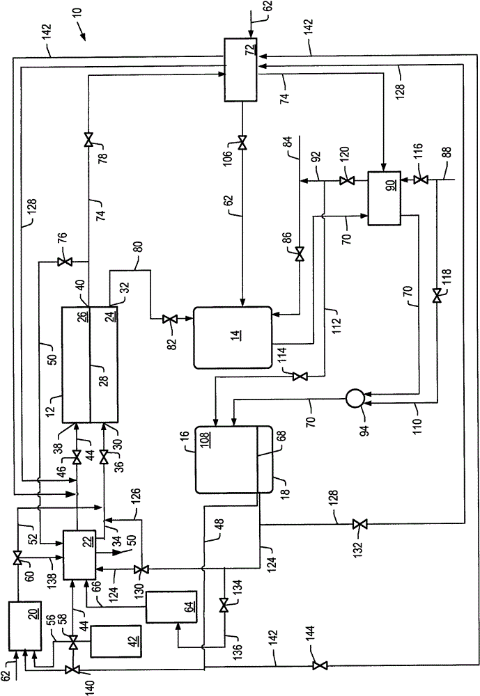
[0190] Example 1 uses the detailed process simulation described above to simulate cell voltage versus current density and power density development for the molten carbonate fuel cell system described herein, where the first reformer is heated by the anode exhaust and no other heating. E.g, figure 1 The system depicted. Heat for the second reformer is heated by exchange with the hot effluent from the catalytic partial oxidation reformer. The output temperature of the effluent from the catalytic partial oxidation reformer is increased by using the cathode exhaust to preheat the catalytic oxidation reformer air feed.

Embodiment 2

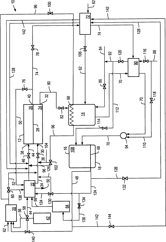
[0191] Example 2 uses the simulations described above to simulate cell voltage vs. current density and power density development for the molten carbonate fuel cell system described herein, with anode exhaust and heat from a catalytic partial oxidation reformer. The first reformer is heated. E.g, figure 2 The system depicted in .

[0192] For Examples 1 and 2, the molten carbonate fuel cell was operated at a pressure of 1 bar (about 0.1 MPa or about 1 atm) and a temperature of 650°C. The flow of feed to the cathode of the molten carbonate fuel cell is countercurrent to the flow of feed to the anode. Air was used as the oxygen source. The values ​​for air were used to generate a molar ratio of carbon dioxide to molecular oxygen of 2 at various hydrogen utilization rates. The percent hydrogen utilization of the molten carbonate fuel cell simulated in Examples 1 and 2, the operating conditions of the first and second reformers, the ratio of steam to carbon, and the ratio of b...

Embodiment 3

[0201] Example 3 is directed to a molten carbonic acid fuel cell system (e.g., figure 1 system depicted in ), the simulations described above were used to determine the current density, cell voltage and power density of a molten carbonate fuel cell operating at 7 bar (about 0.7 MPa or about 7 atm). The molten carbonate fuel cells were operated at 20% or 30% hydrogen utilization at a pressure of 7 bar and a temperature of 650°C. The first reformer had a steam to carbon ratio of 2.5. The temperature of the first reformer is allowed to vary. The second reformer combined with the high temperature hydrogen separation unit has a temperature of 500° C. and a pressure of 15 bar. Air was used as the oxygen source. Values ​​for air were used such that the ratio of carbon dioxide to molecular oxygen in the cathode feed was stoichiometric, thus minimizing cathode side concentration polarization. In all cases, the combined carbon conversion values ​​for the systems using benzene as fee...


PUM

PropertyMeasurementUnit
boiling pointaaaaaaaaaa

Abstract

Processes and systems for operating molNISSAN CHEMICAL IND LTD ten carbonate fuel cell systems are described herein. A process for operating a molten carbonate fuel cell system includes providing a hydrogen-containing stream comprising molecular hydrogen to an anode portion of a molten carbonate fuel cell; controlling a flow rate of the hydrogen-containing stream to the anode such that molecular hydrogen utilization in the anode is less than 50%; mixing anode exhaust comprising molecular hydrogen from the molten carbonate fuel cell with a hydrocarbon stream comprising hydrocarbons, contacting at least a portion of the mixture of anode exhaust and the hydrocarbon stream with a catalyst to produce a steam reforming feed; separating at least a portion of molecular hydrogen from the steam reforming feed; and providing at least a portion of the separated molecular hydrogen to the molten carbonate fuel cell anode.

Description

technical field [0001] The present invention relates to fuel cell systems and methods of operating fuel cells. In particular, the present invention relates to systems and methods of operating molten carbonate fuel cell systems. Background technique [0002] Molten carbonate fuel cells convert chemical energy into electricity. Molten carbonate fuel cells are useful because they deliver high quality reliable electrical power, operate cleanly, and are relatively compact generators. These features make molten carbonate fuel cells attractive for use as a power source in urban areas, ships, or remote areas where sources of electricity supply are limited. [0003] A molten carbonate fuel cell is formed from an anode, a cathode, and an electrolyte layer sandwiched between the anode and cathode. The electrolyte comprises alkali metal carbonates, alkaline earth metal carbonates, molten alkali metal carbonates, or mixtures thereof, which may be suspended in a porous, insulating, and...

Claims


Application Information

Patent Timeline
Patent Type & Authority Applications(China)
IPC IPC(8): H01M8/18
CPCC01B2203/0475C01B2203/048C01B3/382C01B2203/0827C01B2203/148C01B2203/047H01M8/14C01B2203/0405C01B2203/0233C01B2203/0485H01M2008/147C01B2203/142C01B2203/041C01B3/38C01B2203/169C01B3/501C01B2203/0833C01B2203/0283C01B2203/066C01B3/386C01B2203/0883C01B2203/1235C01B2203/0261C01B2203/141Y02E60/526C01B3/48Y02E60/50H01M8/04H01M8/06
Inventor 崔晶瑜E·E·恩沃尔J·W·约翰斯顿M·L·乔施S·L·惠灵顿
Owner SHELL INT RES MAATSCHAPPIJ BV
Why Eureka
Try Eureka