Beam combining, irradiating and receiving system of lasers

A laser beam combining and laser technology, applied in optics, optical components, instruments, etc., can solve the problems of uneven laser energy distribution, difficulty in ensuring optical axis parallelism, laser beam jitter, etc. Laser damage threshold, the effect of expanding the irradiation coverage area

Active Publication Date: 2012-12-05
中国兵器工业第二0五研究所
View PDF3 Cites 19 Cited by
  • Summary
  • Abstract
  • Description
  • Claims
  • Application Information

AI Technical Summary

Problems solved by technology

In this beam combining device, since the parabolic mirror or lens is based on the principle of geometric optics, (1) it is difficult to ensure the parallelism of the optical axes between multiple lasers during installation, resulting in that the energy of the laser spot on the focal plane cannot be concentrated on the focal point , that is, the radial dispersion of the laser spot on the optical axis; (2) the beam divergence angles of multiple lasers are different, and the object distance from the parabolic mirror or lens is different, resulting in the converging laser focusing on different image planes near the focal plane, That is, the laser spot is dispersed in the longitudinal direction of the optical axis; (3) the mode of each laser is unstable, so the energy distribution of the image point near the focal point of the converging laser is unstable; (4) multiple lasers are independent in the radial direction of the optical axis distribution, that is, the energy distribution of the converging laser on the object surface of the parabolic mirror or lens is uneven; (5) the energy density of the laser at the focal point is high, which is easy to break down in the air, causing energy loss; these factors lead to the uneven energy distribution of the combined laser spot and the beam If the divergence angle is too large, the laser beam jitters and the intensity fluctuates, making the distribution of laser energy irradiated on the target uneven and flickering, making it difficult to identify the target image obtained by the sensor and missing small targets
(6) Due to the limitations of the size of the parabolic mirror or lens aperture, the number of lasers is limited, and the combined laser power is limited

Method used


Image

  • Beam combining, irradiating and receiving system of lasers
  • Beam combining, irradiating and receiving system of lasers

Examples


Embodiment Construction

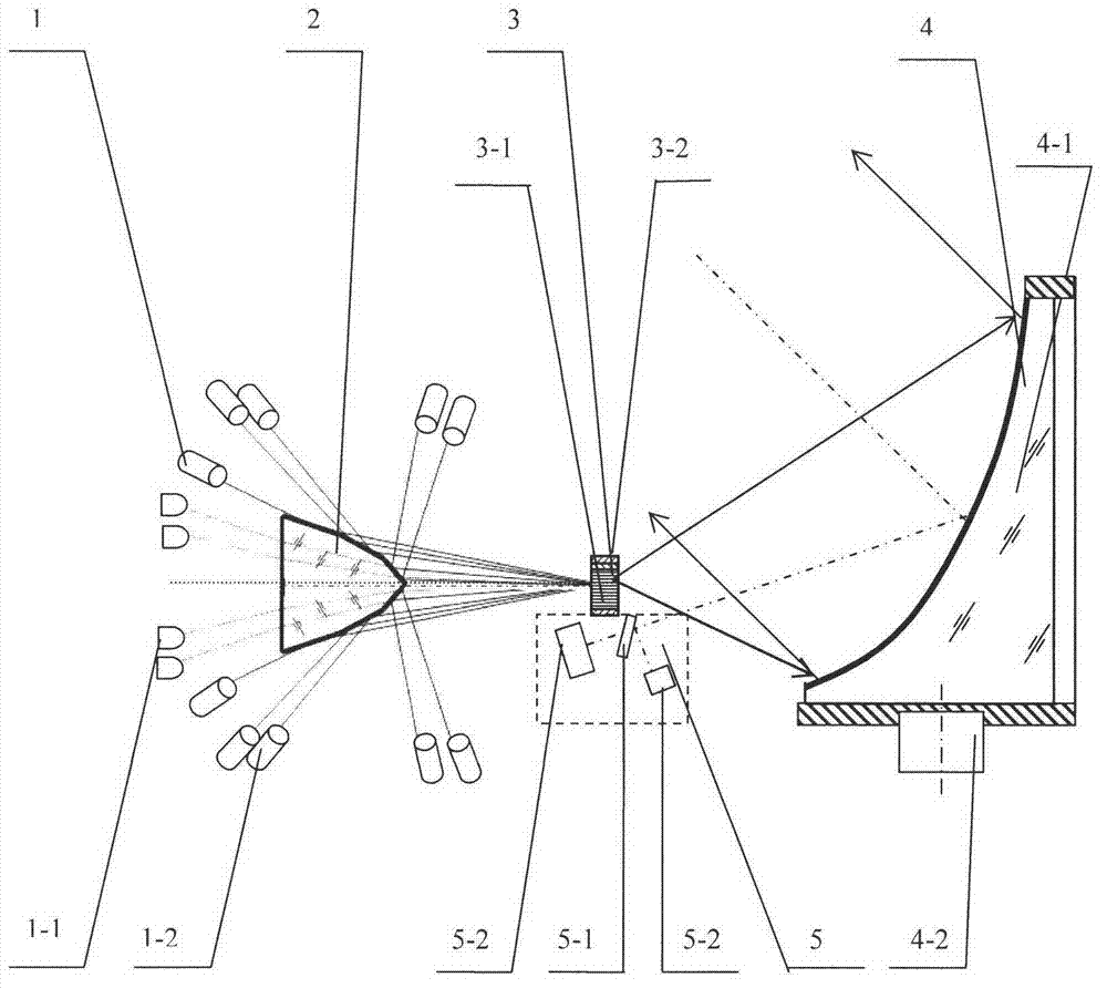
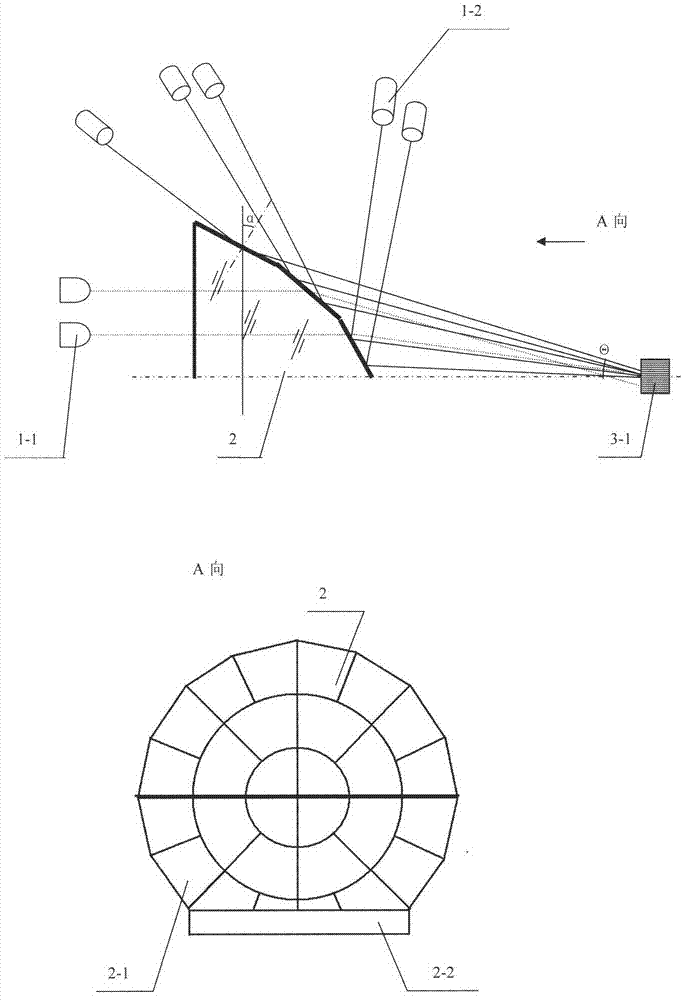
[0021] Attached below figure 1 , attached figure 2 The present invention is described further.

[0022] according to figure 1 As shown, the laser beam combining irradiation and receiving system provided by the present invention includes several laser light sources 1, a multi-dimensional beam combiner 2, a shaper 3, a collimating mirror 4, a receiving and detecting unit 5, and a computer system, which are fixedly connected to a housing . It is characterized in that: said several laser light sources 1 contain several laser light sources of the same or different wavelengths, which can be solid-state laser light sources, gas laser light sources, semiconductor laser light sources, semiconductor laser bars with collimating lenses, etc., the present embodiment Several laser light sources 1 select M semiconductor lasers 1-1 with a wavelength of 0.808 microns and N Q-switched-YAG lasers 1-2 with a wavelength of 1.064 microns, and all lasers are connected to a computer. , pulse wid...


PUM


Abstract

The invention discloses a beam combining, emitting and receiving method of lasers and a system, which belong to the technical field of photoelectricity and are used for carrying out beam combination, emission and reception on multi-beam multi-band high-power lasers. The beam combination, the emission and the reception of lasers in incidence in a plurality of directions are realized by adopting the reflection of a film at the side face of a prism, the incidence and the penetration of an end face, an optical fibre bar and a collimating mirror. The system contains a plurality of laser light sources, a multi-dimensional beam combiner, a shaper, a collimating mirror, a receiving and detecting unit and a computer system. The multi-dimensional beam combiner contains a multi-face prism and a prism holder, wherein the multi-face prism is provided with an end face and a plurality of reflecting mirror faces. A plurality of lasers are irradiated on the end face and the reflecting mirror faces of the multi-dimensional beam combiner from the periphery, the lasers of which the beams are combined are gathered on the input end face of the shaper at an aperture angle smaller than the numerical value of optical fibers, the output lasers are collimated into quasi-parallel light by the collimating mirror for irradiating a target, and the diffuse reflection lasers and the laser-induced radiation patterns of the target are received by the receiving and detecting unit positioned at the position of the focal point of the collimating mirror so as to realize the detection of the target and the acquisition of images.

Description

technical field [0001] The invention belongs to the field of optoelectronic technology, and mainly relates to a combined laser beam irradiation and receiving system, in particular to a laser irradiation and multi-band receiving system in which multiple beams and multi-band laser energies are superimposed and combined into one beam. Background technique [0002] Laser irradiation is an important field of laser application. Actively irradiating the target with laser, improving the contrast between the distant target and the background, implementing laser suppression (including dazzle) on the target, laser radiation or even destruction, and effect evaluation, etc., need to be The coded laser with the smallest spot and the largest power density (maximum energy density) with uniform energy distribution is irradiated on the target, and the target reflects / diffusely emits the laser or the laser-induced radiation is received to realize detection and image acquisition. [0003] Paten...

Claims


Application Information

Patent Timeline
Patent Type & Authority Applications(China)
IPC IPC(8): G02B27/09G02B27/10
Inventor 贾选军南瑶
Owner 中国兵器工业第二0五研究所
Why Eureka
Try Eureka