Method for decreasing carbon deposits on carbon residue removing catalyst of residual oil hydrotreater

A technology of residual oil hydrogenation and treatment device, which is applied in the direction of hydrotreating process, treatment of hydrocarbon oil, petroleum industry, etc. The effect of saving cold hydrogen consumption

Active Publication Date: 2012-12-12
PETROCHINA CO LTD
View PDF7 Cites 8 Cited by
  • Summary
  • Abstract
  • Description
  • Claims
  • Application Information

AI Technical Summary

Problems solved by technology

The content of aromatics in recycled oil is relatively high, and the introduction of recycled oil can increase the dissolving capacity of asphaltenes in residual oil, but the recycled oil and residual oil are introduced into the unit together, and the recycled oil is hydrotreated by protective agent, demetallizer and desulfurizer , a large number of aromatics are hydrogenated, and the degree of aromaticity is greatly reduced. It cannot fully exert its ability to dissolve asphaltenes in the carbon residue removal agent bed and the subsequent catalyst bed, which greatly reduces the effect of the combined process.

Method used


Image

  • Method for decreasing carbon deposits on carbon residue removing catalyst of residual oil hydrotreater
  • Method for decreasing carbon deposits on carbon residue removing catalyst of residual oil hydrotreater
  • Method for decreasing carbon deposits on carbon residue removing catalyst of residual oil hydrotreater

Examples


Embodiment 1

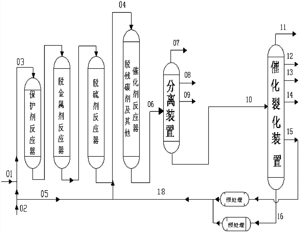
[0041] The residual oil and hydrogen mixed oil directly enter the residual oil hydrogenation pilot plant, and the catalytic cracking and refining are the same as in the comparative example. After mixing with supplementary hydrogen, it enters the residual oil hydrogenation reactor through the front feed port of the carbon removal agent bed, and the same The reaction was carried out according to the conditions in Table 3, and the reaction products were separated into gas, hydrogenated naphtha, hydrogenated diesel oil, and hydrogenated residue.

[0042] From Table 6, we can know that, compared with Comparative Example 1, the carbon deposit of the carbon residue removal agent in Example 1 is 9.5% lower, and the estimated operating period of the catalyst is 1 month longer than that of Comparative Example.

[0043] Table 44000 hours residue hydrogenation product data and catalyst carbon deposition

[0044]

Embodiment 2

[0048] The residual oil and hydrogen mixed oil directly enter the residual oil hydrogenation pilot plant, and the catalytic cracking back to the refining oil is the same as that of the comparative example, and enters the residual oil hydrogenation reactor through the front feed port of the carbon removal agent bed, also according to the conditions in Table 3 The reaction is carried out, and the reaction product is separated into gas, hydrogenated naphtha, hydrogenated diesel oil, and hydrogenated residue.

[0049] From Table 6, we can know that, compared with Comparative Example 2, the carbon deposit of the carbon residue removal agent in Example 2 is 5.2% lower, and the estimated operating period of the catalyst is 1 month longer than that of Comparative Example.

[0050] Table 54,000 hours residue hydrogenation product data and catalyst carbon deposition

[0051]

Embodiment 3

[0055] Residual oil and hydrogen mixed oil directly enter the residual oil hydrogenation pilot plant, catalytic cracking and refining are the same as in the comparative example, enter the residual oil hydrogenation reactor through the front feed port of the desulfurizer bed, and react according to the conditions in Table 3 , The reaction product is separated into gas, hydrogenated naphtha, hydrogenated diesel oil, and hydrogenated residue.

[0056] Through Table 6, we can know that, compared with Comparative Example 3, the carbon deposit of the carbon residue removal agent in Example 3 is 6.5% lower, and the expected operating period of the catalyst is 1.5 months longer than that of Comparative Example.

[0057] Table 64000 hours residue hydrogenation product data and catalyst carbon deposition

[0058]

[0059]


PUM


Abstract

Provided is a method for decreasing carbon deposits on a carbon residue removing catalyst of a residual oil hydrotreater. The method comprises the steps of adding a feeding port in front of a carbon residue removing agent bed layer of the residual oil hydrotreater, introducing catalytic cracking recycle oil with 1-30% of raw residual oil by weight and high aromaticity through the feeding port, improving the dissolving capacity of gradually precipitating asphaltene of the raw residual oil and accordingly decreasing the carbon deposit amount on the catalyst. By means of the method, the carbon residue removing agent and the carbon deposits on the catalyst can be effectively decreased, an operation period of the residual oil hydrotreater can be prolonged, and the cold hydrogen using amount can be decreased.

Description

technical field [0001] The invention relates to a method for reducing carbon deposits in a residual carbon removal catalyst of a residual oil hydrotreating unit. Background technique [0002] At present, the world's oil refining and processing industry is facing the severe challenge of increasingly heavy and inferior crude oil resources. In 2008, my country's crude oil processing volume was 342 million tons, of which heavy crude oil processing volume reached 137 million tons, accounting for more than 40% of the total. As we all know, the proportion of residual oil in crude oil is usually 45-75%, and its properties are significantly inferior to fractions such as gas oil with a lower boiling range. Therefore, the pressure for deep processing of crude oil to maximize the production of light products and chemical raw materials naturally falls on on the residual oil. [0003] At present, it is a relatively advantageous processing route to firstly carry out hydrotreating of resi...

Claims


Application Information

Patent Timeline
Patent Type & Authority Applications(China)
IPC IPC(8): C10G69/04
Inventor 赵愉生崔瑞利于双林谭青峰程涛赵元生范建光张春光张志国那美琦周志远刘元东
Owner PETROCHINA CO LTD
Why Eureka
Try Eureka