Ellipsoid-based reflecting lighting confocal measuring device

A measuring device and ellipsoid technology, applied in the direction of measuring devices, optical devices, instruments, etc., can solve the problem of high difficulty of lighting sources, achieve the effect of improving axial resolution and lateral resolution, and increasing numerical aperture

Inactive Publication Date: 2012-12-12
HARBIN INST OF TECH
View PDF8 Cites 21 Cited by
  • Summary
  • Abstract
  • Description
  • Claims
  • Application Information

AI Technical Summary

Problems solved by technology

[0003] The confocal measurement system using reflective illumination structure can better solve this problem, such as the parabolic reflective system that has been proposed for a period of time and has been developed: using the parabolic reflector to reflect the plane detection light can be placed on the focus of the object to be measured The object is illuminated with a large aperture, but in order to reduce the occlusion ratio of the stage blocking the light source, a large-aperture reflector is used, and it is very difficult to manufacture a large-aperture plane wave illumination source with a matching diameter on the basis of ensuring aberration

Method used


Image

  • Ellipsoid-based reflecting lighting confocal measuring device
  • Ellipsoid-based reflecting lighting confocal measuring device
  • Ellipsoid-based reflecting lighting confocal measuring device

Examples


Embodiment Construction

[0013] The embodiments of the present invention will be described in detail below with reference to the accompanying drawings.

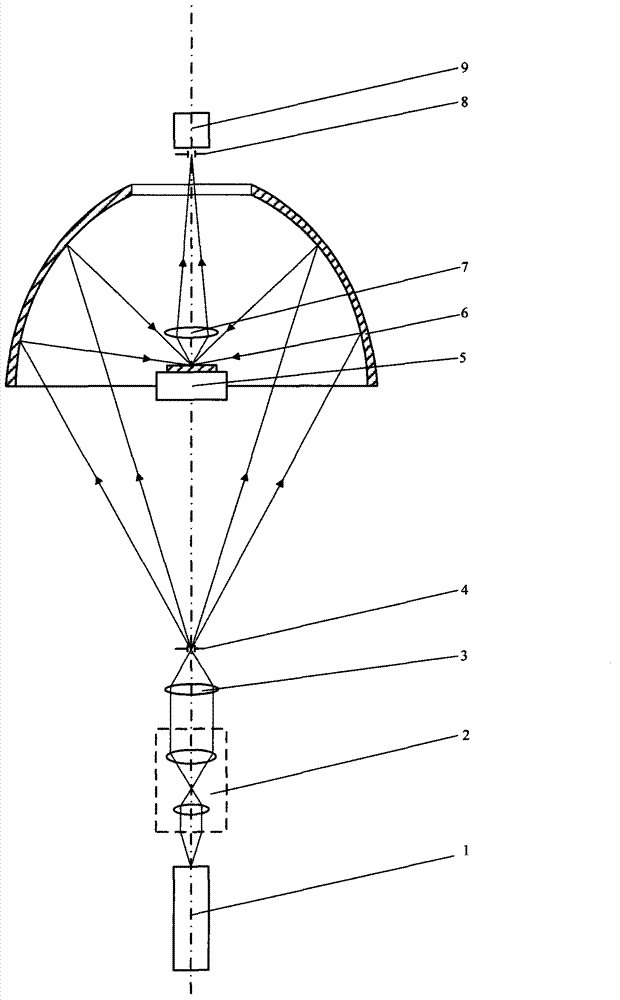
[0014] A confocal measurement device based on ellipsoid reflection illumination includes a laser 1, a collimating beam expander 2 sequentially arranged on the direct light path of the laser 1, a large numerical aperture focusing objective 3, a pinhole 4, a three-dimensional micro-displacement stage 5, Focusing objective lens 7, detection pinhole 8 and detector 9; on the direct light path of the laser 1, an ellipsoid mirror 6 is arranged between the focusing objective lens 7 and the detection pinhole 8, and the far focus of the ellipsoid mirror 6 is located at The pinhole 4 position, the near focus is on the sample surface placed on the three-dimensional micro-displacement stage 5 .

[0015] When measuring work:

[0016] The first step is to illuminate the sample under test.

[0017] like figure 1 As shown, the laser 1 emits a parallel probe beam, ...


PUM


Abstract

The invention discloses an ellipsoid-based reflecting lighting confocal measuring device, belonging to an optics microtechnique. A collimation beam expander, a large numerical aperture focusing objective lens, a pinhole, a three-dimensional micrometric displacement objective table, a focusing objective lens, a detecting pinhole and a detector are arranged on a laser direct light path in sequence; an ellipsoid reflecting lens is configured on the laser direct light path and at a position between the focusing objective lens and the detecting pinhole; a remote focus of the ellipsoid reflecting lens is located on the pinhole; a near focus of the ellipsoid reflecting lens is located on a surface of a sample arranged on the three-dimensional micrometric displacement objective table. With the adoption of the ellipsoid-based reflecting lighting confocal measuring device, a defect that an axial resolution force in a traditional confocal measuring technology is limited by an objective lens numerical aperture is overcome, lighting to large numerical apertures is realized, so that a transverse resolution force and the axial resolution force of a system are greatly improved.

Description

technical field [0001] The invention belongs to the field of optical microscopic measurement, and mainly relates to an ultra-precision non-contact measurement device used for measuring the surface topography of a three-dimensional microstructure in a microstructure industrial sample. Background technique [0002] Confocal scanning measurement is one of the important technical means to measure 3D microstructure, microstep, microgroove line width, depth and surface shape in the fields of micro-optics, micro-mechanics and micro-electronics. Including differential confocal radius of curvature measurement method and device (publication number CN101526341), confocal microscope and method for measuring height with the same (publication number CN1392962), polychromatic super-resolution differential confocal measurement method and device (publication number CN101182992) For the confocal scanning measurement system using traditional lens illumination structure, its axial resolution an...

Claims


Application Information

Patent Timeline
Patent Type & Authority Applications(China)
IPC IPC(8): G01B9/04G01B11/30
Inventor 刘俭谭久彬谭欣然
Owner HARBIN INST OF TECH
Why Eureka
Try Eureka