Desulfuration and impurity removal device and process of tunnel kiln exhaust gas

A tunnel kiln and waste gas technology, applied in waste heat treatment, furnace types, furnaces, etc., can solve the problems of poor absorption of sulfur dioxide or smoke, low desulfurization and dust removal efficiency, easy vaporization of lime water, etc., and achieves small footprint and reasonable design. , the effect of reducing pollution

CN102829624BActive Publication Date: 2014-05-21黎志登 +1
4 Cites 0 Cited by

Patent Information

Authority / Receiving Office
CN · China
Patent Type
Patents(China)
Current Assignee / Owner
Publication Date
2014-05-21

Smart Images

  • Figure 1
    Figure 1
  • Figure 2
    Figure 2
  • Figure 3
    Figure 3
Patent Text Reader

Abstract

The invention relates to the technical field of waste gas treatment, and particularly relates to a desulfuration and impurity removal device and process of tunnel kiln exhaust gas. The process comprises the following steps that: A. part of exhaust gas generated in a high temperature baking area is introduced pinto a drying buffer area, the exhaust gas passes through a brick mesh of the drying buffer area and is then discharged from an exhaust gas collection channel; B. another part of exhaust gas generated in the high temperature baking area enters a side air duct through an air duct port, a ventilating gate is opened, cold air outside a tunnel kiln enters the side air duct through a ventilating gate port and is mixed with the exhaust gas in the side air duct, and the mixed exhaust gas enters the high temperature baking area again through the air duct port; C. the ventilating gate is closed, the exhaust gas enters the side air duct through the air duct port, and when the mixed exhaust gas reaches the side air duct of a drying area, the mixed exhaust gas is pumped from the air duct port to the drying area, and the mixed exhaust gas passes the brick mesh of the drying area; and D. the exhaust gas is pumped by a exhaust fan and discharged from the exhaust gas collection channel. The desulfuration and impurity removal device and process of tunnel kiln exhaust gas provided by the invention is good in a dedusting effect and high in desulfuration efficiency, and the sulfur content of the exhaust gas is reduced by 80%-90%.
Need to check novelty before this filing date? Find Prior Art

Description

technical field

[0001] The invention relates to the technical field of waste gas treatment, in particular to a desulfurization and impurity removal device and process for tunnel kiln waste gas. Background technique

[0002] As an environmentally friendly and energy-saving brick kiln, the tunnel kiln has gradually replaced the traditional wheel kiln in our country and has become the main brick kiln in our country. The combustion products of the tunnel kiln have caused serious pollution to the atmosphere, affecting human survival and quality of life. For example, the sulfur in the fuel of the tunnel kiln forms acid rain in the atmosphere, which reduces agricultural production. In addition, the sulfur in the exhaust gas discharged from the tunnel kiln Harmful fine dust affects human health and pollutes the environment. To this end, people use some desulfurization and dust removal methods to treat the tunnel kiln exhaust gas, so that the tunnel kiln exhaust gas can be discharge...

Examples

Embodiment 1

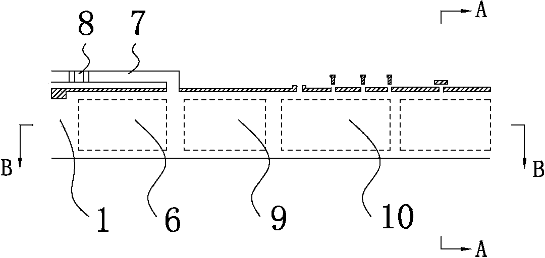
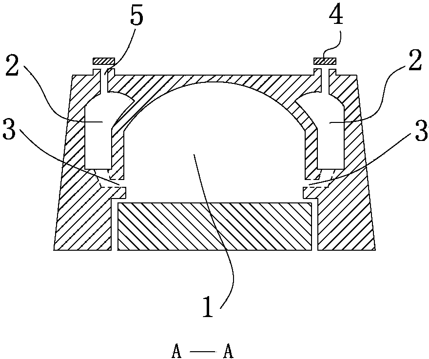
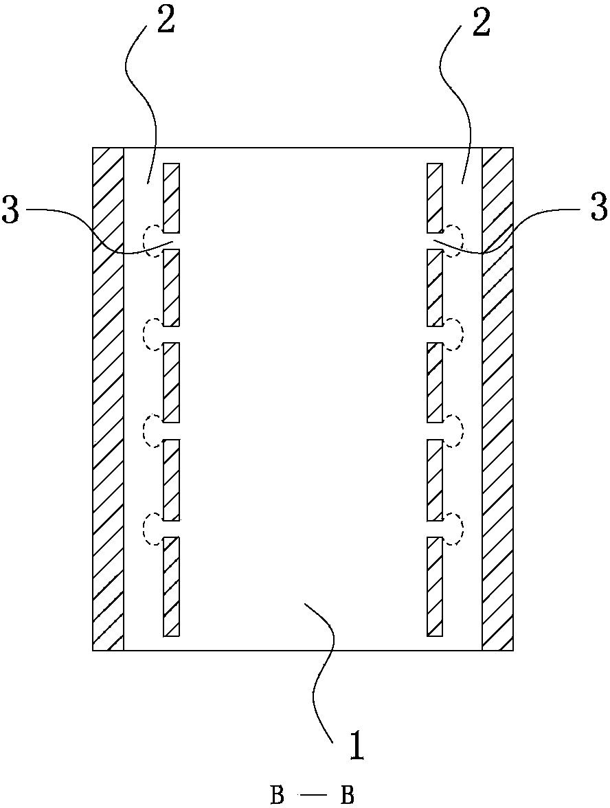
[0030] Such as Figure 1 to Figure 3 As shown, a desulfurization and impurity removal device for tunnel kiln exhaust gas in this embodiment includes a direct-fired tunnel 1, and the direct-fired tunnel 1 includes a drying zone 9 and a high-temperature firing zone 10 arranged in sequence. The direct firing tunnel 1 also includes a drying buffer zone 6, a waste gas collection channel 7 and a brick net, the drying buffer zone 6 is arranged in front of the drying zone 9, and the drying buffer zone 6 and the waste gas The collection channel 7 is connected, the brick net is set in the direct-fired tunnel 1, the desulfurization and impurity removal device also includes a side air channel 2, an air channel opening 3 and a ventilation gate 4, and the side air channel 2 is opened in the Inside the kiln walls on both sides of the direct firing tunnel 1, the top of the side air duct 2 is provided with an air gate 5, the air gate 4 is movably arranged on the air gate 5, and the air duct 3 ...

Embodiment 2

[0038] The difference between this embodiment and Embodiment 1 is that: the brick network in this embodiment also includes a first bridge 13, and the first bridge 13 is horizontally laid on the top of the brick row, and the first bridge 13 is A brick, the brick network also includes a second bridge 14, the second bridge 14 is arranged between the 7th and the 8th layer brick network layer, and the second bridge 14 is two bricks placed in parallel piece. The first bridge 13 at the top of the brick column is used to stabilize the brick column and reduce the gap, and the second bridge 14 can firmly support the brick layer stacked on the second bridge 14, so that the structure of the brick column is more stable, and then the brick network is ensured. Filtering effect.

[0039] Other structures of this embodiment are the same as those of Embodiment 1, and will not be repeated here.