Method used for increasing wind generating set system damping and tuning quality damper

A technology for tuning mass damping and wind turbines, which is applied to wind turbine components, wind engines, and wind power generation, and can solve problems such as increasing wind turbine system damping, reducing power generation, and reducing power generation efficiency to achieve vibration reduction effects Visible, vibration-suppressing, and negative-effect suppressing effects

Active Publication Date: 2012-12-26
ZHUZHOU TIMES NEW MATERIALS TECH +1
View PDF5 Cites 9 Cited by
  • Summary
  • Abstract
  • Description
  • Claims
  • Application Information

AI Technical Summary

Problems solved by technology

[0006] Aiming at the technical defects that the blades of the existing wind power generator set stall and cause the system damping to drop and cause vibration, and the current method of sticking speed strips on the blades will reduce the power generation efficiency and reduce the amount of power generation, the present invention proposes a method for increasing wind power generators. A method for system damping and a tuned mass damper for realizing the method. The method of the invention has the advantages of easy implementation and good damping effect, and the damper has the advantages of reasonable structure, obvious damping effect and convenient maintenance.

Method used


Image

  • Method used for increasing wind generating set system damping and tuning quality damper
  • Method used for increasing wind generating set system damping and tuning quality damper
  • Method used for increasing wind generating set system damping and tuning quality damper

Examples


Embodiment 1

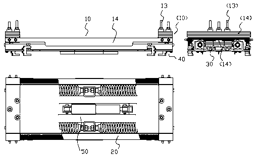
[0036] Such as figure 2As shown, the tuned mass damper includes: a bearing support structure 40 , a linear guide rail pair 30 , a mass block 10 , a hydraulic damping system 50 and a steel spring system 20 .

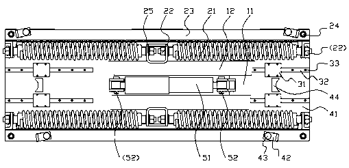
[0037] Such as image 3 As shown, wherein, the bearing support structure 40 includes: a support plate 41, a locking device 42, a mounting screw 43, and a limit protection 44;

[0038] The hydraulic damping system 50 includes: a hydraulic damper 51, a fixed pin 52;

[0039] The mass system 10 includes: a mass base 11, a spring adapter plate 12, a screw 13, and an adjusting mass 14;

[0040] The steel spring system 20 includes: steel springs 21 , mounting nuts 22 , fixing plates 23 , mounting bolts 24 , and connecting plates 25 . Among them, such as Figure 4 As shown, the steel spring 21 consists of a spring 211 and a bolt joint 212 . The bolt joints 212 of the two steel springs 21 are screwed into the mounting nuts 22 through the connecting plate 25, and connected t...

Embodiment 2

[0050] Such as Figure 6 As shown, the tuned mass damper includes a bearing support structure 40, a linear guide rail pair 30, a mass block system 10, and an elastic rubber 20;

[0051] Such as Figure 7 As shown, the bearing support structure 40 includes: a support plate 41, a locking device 42, a mounting screw 43, and a limit protection 44;

[0052] The linear guide pair 30 includes: a guide rail 32, a slider 31, and a mounting screw 33;

[0053] The mass system 10 includes: a mass base 11, an adapter plate 12, a screw 13, an adjusting mass 14, and mounting screws 15;

[0054] The specific connections of the components of the tuned mass damper described in this example are:

[0055] 1. The support plate 41 is fixed on the frame through the locking device 42, and the limit protection 44 is used to ensure the reciprocating operation of the mass block system 10 within the safe stroke.

[0056] 2. The guide rail 31 is fixed on the support plate 41 through the mounting screw...


PUM


Abstract

The invention discloses a method used for increasing wind generating set system damping and a tuning quality damper. The tuning quality damper is arranged on the tail portion of a machine frame of a wind generating set. By regulating inherent frequency of the tuning quality damper, shimmy frequency of the tuning quality damper is identical with or close to that of the machine frame. When the machine frame and the tuning quality damper are in sympathetic vibration, phase angles are different. By utilizing damping provided by the tuning quality damper to absorb shimmy energy of blades, the structure of a wind driven generator can be protected effectively, the problem that the wind generating set halts frequently is eliminated, service life of the wind generating set is prolonged, and no influence on generating efficiency of the wind generating set exists at the same time.

Description

technical field [0001] The invention belongs to the technical field of vibration reduction of engineering structures, and specifically relates to a method for increasing the damping of a wind power generator system and a tuned mass damper, which are mainly used for the vibration reduction of wind power generators, and can also be used in bridges, high-rise buildings and other projects . Background technique [0002] For fixed-pitch stall-controlled wind turbines, when the ambient temperature is lower than -20°C and the wind speed exceeds the rated point (about 16-25m / s), during the normal operation of the wind turbine, irregular and unexpected The predicted instantaneous vibration phenomenon of the blade, that is, the shimmy vibration of the blade in the rotation plane, sometimes diverges, causing the vibration of the unit to increase rapidly, causing the unit to shut down and affecting the normal power generation of the unit. At the same time, this vibration is also harmfu...

Claims


Application Information

Patent Timeline
IPC IPC(8): F16F15/02F03D11/00
CPCY02E10/722
Inventor 谢凌志林胜胡伟辉程海涛曹宇君荣继刚谢宇丹毛俊宁响亮查国涛于松林刘河张才盛李祺王海蛟
Owner ZHUZHOU TIMES NEW MATERIALS TECH
Why Eureka
Try Eureka