Low-energy consumption vacuum suction drainage control system

A technology for controlling system and vacuum degree, applied in dewatering/drying/concentrating sludge treatment, etc., can solve the problems of complex structure of dewatering system, unstable product quality, bulky equipment, etc., to achieve simple structure, stable product quality, energy low cost effect

Active Publication Date: 2013-01-02
WUXI JINHE TECH
View PDF7 Cites 2 Cited by
  • Summary
  • Abstract
  • Description
  • Claims
  • Application Information

AI Technical Summary

Problems solved by technology

[0006] The purpose of the present invention is to address the above problems, to provide a low-energy vacuum suction and drainage control system to solve the problems o...

Method used


Image

  • Low-energy consumption vacuum suction drainage control system

Examples


Embodiment Construction

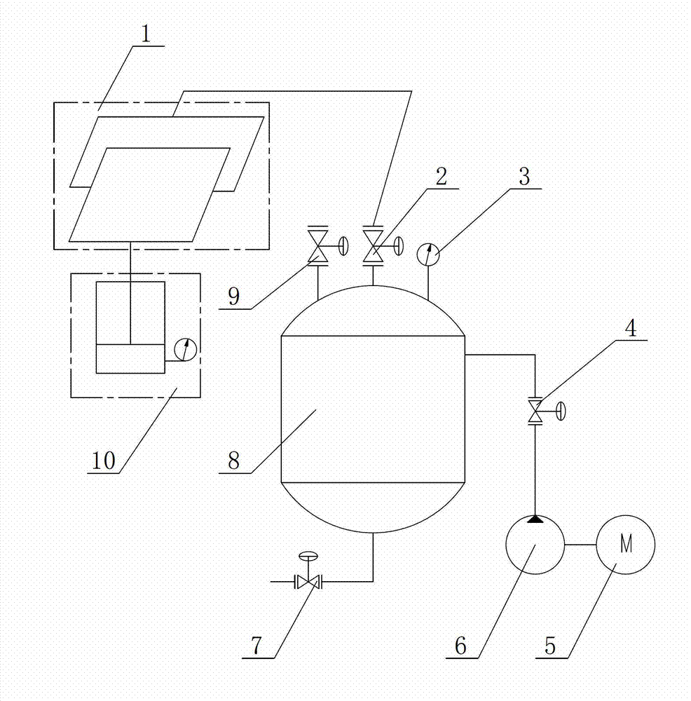
[0017] The technical solutions of the present invention will be further described below in conjunction with the accompanying drawings and through specific implementation methods.

[0018] Please refer to figure 1 as shown, figure 1 It is a structural schematic diagram of the low-energy vacuum suction and drainage control system of the present invention; in this embodiment, a low-energy vacuum suction and drainage control system includes a mold cavity assembly 1, and a pressure point signal is provided on the mold cavity assembly 1 platform 10, the pressure point signal platform 10 is electrically connected to the controller, the mold cavity assembly 1 is connected to the vacuum tank 8 through a pipeline, and the pipeline between the mold cavity assembly 1 and the vacuum tank 8 is provided with a control valve 2, the The control valve 2 is electrically connected to the controller, and the bottom of the vacuum tank 8 is provided with a drain pipe and a drain valve 7, and the va...


PUM


Abstract

The invention discloses a low-energy consumption vacuum suction drainage control system. The low-energy consumption vacuum suction drainage control system comprises a mold cavity assembly. The mold cavity assembly is provided with a pressure spot signal station. The pressure spot signal station is electrically connected to a controller. The mold cavity assembly is connected to a vacuum tank by a pipe. A control valve is arranged at the pipe between the mold cavity assembly and the vacuum tank. The control valve is electrically connected to the controller. The bottom of the vacuum tank is provided with a drainage pipe and a drainage valve. The vacuum tank is connected to a vacuum pump unit by a pipe. The vacuum pump unit is driven by a motor and is electrically connected to the controller. An upper end of the vacuum tank is provided with a safety valve and a pressure instrument. The safety valve and the pressure instrument are electrically connected to the controller. The low-energy consumption vacuum suction drainage control system has a simple structure, realizes suction drainage by a pressure difference formed between the vacuum tank and the mold cavity assembly, has low power consumption, reliable operation performances and low energy consumption, and realizes stable product quality after dehydration and product water content less than 40%.

Description

technical field [0001] The invention relates to a suction and drainage control system, in particular to a vacuum suction and drainage control system with low energy consumption. Background technique [0002] As the country's efforts to protect the environment continue to increase, the sludge in sewage treatment requires deep dehydration for subsequent treatment; at present, most domestic manufacturers use pressing, extrusion, and traditional drying processes to Step-by-step control, however, this kind of dehydration process also has the following shortcomings: [0003] 1. The equipment used in the whole process is bulky and complex in structure; [0004] 2. Large energy consumption; [0005] 3. The moisture content of the product is more than 50%, and the product quality is unstable. Contents of the invention [0006] The purpose of the present invention is to address the above problems, to provide a low-energy vacuum suction and drainage control system to solve the pro...

Claims


Application Information

Patent Timeline
IPC IPC(8): C02F11/12
Inventor 张佑四曹旭明王荣伟钟伟良
Owner WUXI JINHE TECH
Why Eureka
Try Eureka