Environmental-combustion burner

A burner and environmental protection technology, applied in the direction of gas fuel burners, burners, combustion methods, etc., can solve the problems of short flame holes, high temperature at the bottom of the pot, and inability to achieve environmentally friendly combustion.

Inactive Publication Date: 2013-01-02
福建省江南电器制造有限公司
View PDF1 Cites 8 Cited by
  • Summary
  • Abstract
  • Description
  • Claims
  • Application Information

AI Technical Summary

Problems solved by technology

[0006] The purpose of the present invention is to provide a kind of burning environment-friendly burner, to solve the problem that in the prior art, the flame holes in the first air cavity area produce longer flames,

Method used


Image

  • Environmental-combustion burner
  • Environmental-combustion burner

Examples


Embodiment Construction

[0020] In order to further explain the technical solution of the present invention, the present invention will be described in detail below through specific examples.

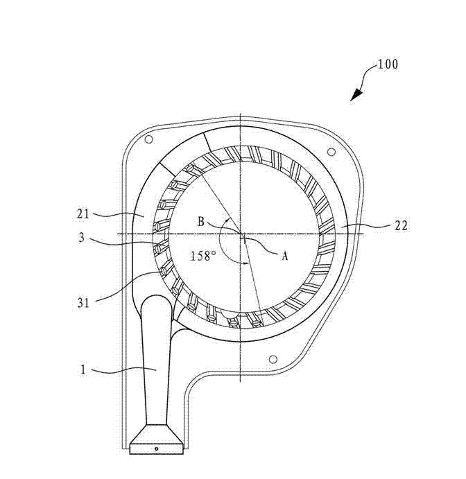
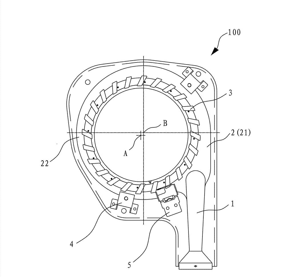
[0021] Such as figure 1 and figure 2 As shown, the present invention relates to an environmentally friendly burner, which is divided into a burner upper plate and a burner lower plate that can be covered together. Forming, the burner upper plate is also formed with an energy-gathering ring support 4 and a thermocouple support 5.

[0022] Wherein, the burner specifically includes an introduction pipe 1 for introducing a mixture of gas and primary air, an annular distribution pipe 2 connected to the introduction pipe 1, and a plurality of flame holes 3 arranged on the inner peripheral side of the annular distribution pipe 2, Specifically the same as the background technology, the flame hole 3 also includes an upper flame hole 3 and a lower flame hole 3, and the annular distribution pipe 2 has a first air cavit...


PUM


Abstract

The invention discloses an environmental-combustion burner which comprises an ingress pipe, a circular distribution pipe, and a plurality of flame holes. The ingress pipe guides in mixed gas of fuel gas and primary air. The circular distribution pipe is connected with the ingress pipe. The flame holes are arranged on the inner peripheral side of the circular distribution pipe. The circular distribution pipe is provided with a first gas cavity area close to the ingress pipe, and a second gas cavity area away from the ingress pipe. The center of a circle of the flame holes is eccentric to the center of a circle of the outer peripheral side of the circular distribution pipe and is close to the second gas cavity area. The length of flames generated in the flame holes in the first and second gas cavity areas of the environmental-combustion burner can be balanced, so that high temperature of a heated boiler bottom tends to be consistent. Local high temperature of the heated boiler bottom is avoided, carbon oxides and nitrogen oxides which are harmful to the environment and generated in combustion of the fuel gas are reduced effectively, and the combustion requirement of the burner for environment friendliness is met.

Description

technical field [0001] The present invention relates to an internal flame burner arranged on a stove, and more specifically relates to an environmentally friendly burner, which ensures the combustion flame energy of each fire hole in the circumference of the burner through structural design. More uniform and consistent, reducing the generation of carbon oxides and nitrogen oxides. Background technique [0002] The traditional burner is generally a split burner composed of a copper splitter and a cast iron injector, which is heavy in weight, high in cost, and low in thermal efficiency, generally only about 55%, which is not energy-saving; in addition, the user After a long time of use, water and other dirt will block the fire hole, and dripping water will fall into the cast iron ejector through the fire hole of the copper firearm. The cast iron is easy to rust, and the CO2 of the flue gas is prone to exceed the standard. Sometimes it is red and sometimes black smoke, which is...

Claims


Application Information

Patent Timeline
IPC IPC(8): F23D14/02F23D14/84
Inventor 程志旭
Owner 福建省江南电器制造有限公司
Why Eureka
Try Eureka