Processing method for vacuum drying impregnation of capacitor

A treatment method, vacuum drying technology, applied in the field of vacuum drying and impregnation of capacitors, can solve the problems of low production efficiency, affecting the quality and life of power capacitors, and long time, and achieve the effect of improving sufficient infiltration and swelling

Inactive Publication Date: 2013-01-02
ENERTECH SUZHOU ENERGY TECH CO LTD
View PDF4 Cites 20 Cited by
  • Summary
  • Abstract
  • Description
  • Claims
  • Application Information

AI Technical Summary

Problems solved by technology

[0002] At present, in the production process of power capacitor manufacturers, vacuum degassing, drying and impregnation of power capacitors are all done by placing the semi-finished products of power capacitors in a vacuum tank and adopting double pumping single injection or group pumping single injection or group pumping soaking method. The impregnation quality of the product is related to the degree of vacuum, temperature and time, especially the degree of vacuum. However, due to the large space of the entire vacuum impregnation system and the fact that there are many air leakage points, it is difficult to ensure the tightness, and all materials will decompose in an extremely high vacuum environment. Gas and liquid media are limited by the existence of saturated vapor pressure and the ultimate vacuum degree of the vacuum equipment itself, so the improvement of the vacuum degree is limited. The existing equipment can reach a vacuum degree of 0.1 Pa. Therefore, the product performance can be improved by increasing the vacuum degree It is close to its limit; on the other hand, the gap between the solid dielectric layers of the capacitor element is very small, generally only 0.5-1.5 μm, and at the same time, the liquid medium has a certain viscosity, such as being sealed by the liquid medium between the solid medium layers and between the solid medium and the aluminum foil layer A small amount of low-vacuum gas (bubble) is difficult to be expelled and filled with liquid medium. The main purpose of vacuum impregnation treatment of power capacitors is to remove the gap between the solid dielectric layer of the capacitor element and the gap between the dielectric layer and the aluminum foil layer of the plate. The air is completely squeezed out and filled with high-quality liquid medium, and if there are bubbles between the solid medium layer and the medium and the aluminum foil layer, even if there are very few such bubbles, the quality and life of the power capacitor will be seriously affected; again, now In the prior art, the applicant believes that the insulating medium oil and the solid medium are not fully infiltrated, thereby restricting the further improvement of product performance; thirdly, the insulating medium oil of the power capacitor has a certain viscosity, such as being sealed in the solid medium layer by the liquid medium and between the solid and the aluminum foil layer A small amount of low-vacuum gas (bubble) is difficult to be squeezed out at this time and filled by the liquid medium, and if there are bubbles between the solid medium layer and between the solid medium and the aluminum foil layer, there are very few such bubbles. Will seriously affect the quality and life of power capacitors
Thirdly, the existing power capacitor vacuum impregnation process takes about 72h to 96h, which is generally longer, with low production efficiency, high energy consumption and poor economic benefits.

Method used


Image

  • Processing method for vacuum drying impregnation of capacitor

Examples


Embodiment 1

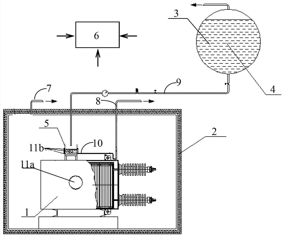
[0026] Embodiment 1: A treatment method for vacuum drying and impregnation of capacitors. This treatment method is based on an impregnation device, which includes a vacuum tank 2 for placing a power capacitor 1 and a vacuum oil storage tank 4 for storing insulating medium oil 3 And be positioned at the small oil sump 5 in the vacuum tank 2 and above the power capacitor 1, a vacuum pump system 6 is connected to the vacuum tank 2 and the power capacitor 1 through an air extraction pipe 7 and an air extraction oil injection pipe 8 respectively; The insulating medium oil 3 in the vacuum oil storage tank 4 is transferred to the small oil tank 5, and the bottom of the small oil tank 5 is connected to the pumping oil injection pipe 8 through an oil injection pipe 10; the outer wall of the power capacitor 1 is provided with an ultrasonic generating part 11a ;

[0027] The processing method comprises the following steps:

[0028] Step 1. Place the power capacitor 1 to be processed in ...

Embodiment 2

[0036] Embodiment 2: A treatment method for vacuum drying and impregnation of capacitors. This treatment method is based on an impregnation device, which includes a vacuum tank 2 for placing a power capacitor 1 and a vacuum oil storage tank 4 for storing insulating medium oil 3 And be positioned at the small oil sump 5 in the vacuum tank 2 and above the power capacitor 1, a vacuum pump system 6 is connected to the vacuum tank 2 and the power capacitor 1 through an air extraction pipe 7 and an air extraction oil injection pipe 8 respectively; The insulating medium oil 3 in the vacuum oil storage tank 4 is transferred to the small oil tank 5, and the bottom of the small oil tank 5 is connected to the pumping oil injection pipe 8 through an oil injection pipe 10;

[0037] The processing method comprises the following steps:

[0038] Step 1. Place the power capacitor 1 to be processed in the vacuum tank 2, and evacuate both the power capacitor 1 and the vacuum tank 2 to form a 0.0...


PUM


Abstract

The invention discloses a processing method for vacuum drying impregnation of a capacitor. The method comprises the following steps of heating a power capacitor to 80-90 DEG C; cooling the internal temperature of the power capacitor to 70-80 DEG C, and improving the vacuum degree of the gas partial pressure in a vacuum tank to 0.5-1 Pa step by step; opening an ultrasonic generating component which is arranged on the external wall of the power capacitor, and cooling the internal temperature of the power capacitor to 40-60 DEG C, and reducing the gas partial pressure of the vacuum tank at 0.2-0.5 Pa, and meanwhile slowly pouring insulating medium oil in the power capacitor shell for 8-22 h; after the internal part of the power capacitor is filled with the insulating medium oil, maintaining the opening state of the ultrasonic, reducing the internal temperature of the power capacitor, maintaining the internal temperature at 30-40 DEG C, and controlling the vacuum degree of the gas partial pressure in the vacuum tank about 0.2-0.5 Pa. According to the processing method provided by the invention, the gas integrated into the insulation medium oil and the local few low vacuum gas which is sealed between solid medium layers and between medium and aluminum foil layers by the insulation medium oil can be exhausted more easily.

Description

technical field [0001] The invention relates to a treatment method for vacuum drying and impregnation of capacitors, belonging to the technical field of power capacitors. Background technique [0002] At present, in the production process of power capacitor manufacturers, vacuum degassing, drying and impregnation of power capacitors are all done by placing the semi-finished products of power capacitors in a vacuum tank and adopting double pumping single injection or group pumping single injection or group pumping soaking method. The impregnation quality of the product is related to the degree of vacuum, temperature and time, especially the degree of vacuum. However, due to the large space of the entire vacuum impregnation system and the fact that there are many air leakage points, it is difficult to ensure the tightness, and all materials will decompose in an extremely high vacuum environment. Gas and liquid media are limited by the existence of saturated vapor pressure and ...

Claims


Application Information

Patent Timeline
Patent Type & Authority Applications(China)
IPC IPC(8): H01G13/04
Inventor 李子华
Owner ENERTECH SUZHOU ENERGY TECH CO LTD
Why Eureka
Try Eureka