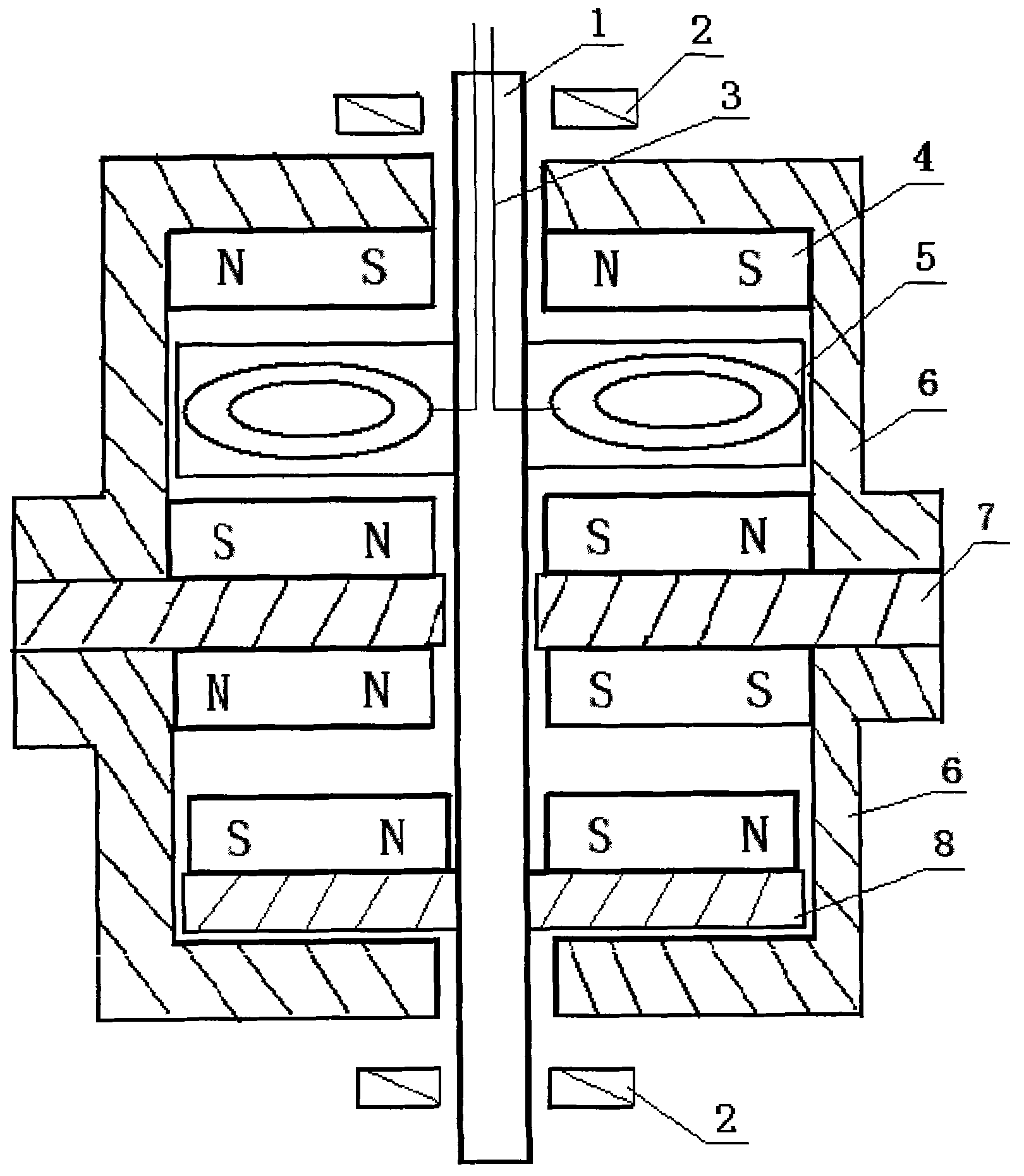
Permanent magnet frequency conversion power generator
A technology of permanent magnets and generators, applied in the fields of thermal wind power or hydropower, and variable frequency generators, which can solve the problems of insufficient efficiency and large frictional resistance.
- Summary
- Abstract
- Description
- Claims
- Application Information
AI Technical Summary
Problems solved by technology
Method used
Image
Examples
Embodiment 1
[0033] Select high-quality silicon steel sheets containing a moderate amount of silicon to punch out 48-slot motor winding off-line punches with an outer diameter of 20 cm, an inner diameter of 15 cm, and an outward notch, and laminate them to form a stator core with a thickness of 3.5 cm. The inner diameter is The iron plate is clamped to facilitate the installation of the fixed shaft, which is beneficial to install the motor on the fixed frame. The motor can be prepared as a 500W / 24V two-pole three-phase AC rated output power variable frequency generator, and the lower coil winding of the stator Line, after calculating the diameter of the wire and the number of turns per slot from the relevant power calculation formula, the coil is rolled off in double-layer stacked winding with a span of 1-2 slots. Each pole and each phase occupy four consecutive slots, and the three phases alternate according to the phase. The number of pole pairs is accurately off-line, and finally connect...
Embodiment 2
[0036] About the method of exempting the iron core frequency conversion generator from silicon steel sheet punching:
[0037] The newly designed frequency conversion generator has completely changed the traditional way of manufacturing the iron core of the motor by punching out the groove shape with silicon steel sheet and then laminating it into the motor core. Power output for power supply.
[0038] 1). Preparation of fixed shaft:
[0039] Use carbon knot steel to cut out the corresponding space on the machine tool according to the design drawing, including the end cover positions with permanent magnets attached to both ends, the bearing positions, the fixed winding coil positions and the magnetic push-pull component positions. The shaft is hollow so that the power supply wire can be led out to have a channel.
[0040] 2). The method of making the generator coil winding:
[0041] According to the rated output power of the generator, the number of motor phases, output volt...
Embodiment 3
[0050] At present, domestic solar energy is used in lighting. The applied solar power generation system is sent to the storage battery to drive the lamps to work. Generally, the voltage of 12VDC. 24VDC. -6V can get more perfect effect. Therefore, the solar radiation conversion ability of the solar panel is 18VDC for the charging voltage of the 12V storage battery. In order to realize the voltage output of the variable frequency generator is the same as that of the solar battery, so as to achieve the power consumption effect of wind and solar complementarity, the operation process of this embodiment is: select the frequency conversion The outer diameter of the stator chip of the generator is 11Cm, and it goes out of the 12 slots of the outward-facing motor, and the thickness of the stack is 3.0Cm. The diameter of the wire and the number of turns per volt are calculated according to the rated power 300W36V voltage output formula. Layer winding off the line, two-way parallel conn...
PUM
 Abstract
Description
Claims
Application Information
 - R&D
- Intellectual Property
- Life Sciences
- Materials
- Tech Scout
- Unparalleled Data Quality
- Higher Quality Content
- 60% Fewer Hallucinations
Browse by: Latest US Patents, China's latest patents, Technical Efficacy Thesaurus, Application Domain, Technology Topic, Popular Technical Reports.
© 2025 PatSnap. All rights reserved.Legal|Privacy policy|Modern Slavery Act Transparency Statement|Sitemap|About US| Contact US: help@patsnap.com

