High-birefringence photonic crystal optical fiber low in limit loss

A technology of photonic crystal fiber and high birefringence, which is applied in polarizing fiber, cladding fiber, optical waveguide light guide, etc., can solve the problems of low birefringence of photonic crystal fiber, achieve small influence of temperature, limit loss low, high birefringence The effect of refraction

Inactive Publication Date: 2013-01-09
TIANJIN UNIVERSITY OF TECHNOLOGY
View PDF5 Cites 17 Cited by
  • Summary
  • Abstract
  • Description
  • Claims
  • Application Information

AI Technical Summary

Problems solved by technology

[0006] The purpose of the present invention is to solve the problem of low birefringence of the existing photonic crystal fiber, to provide a photonic crystal fiber with high birefringence and low confinement loss, which has a simple structure and is easy to manufacture. The structure of the fiber itself has double rotational symmetry, and can obtain Higher birefringence than the existing birefringent photonic crystal fiber, and the confinement loss is very low, and the dispersion is flat

Method used


Image

  • High-birefringence photonic crystal optical fiber low in limit loss
  • High-birefringence photonic crystal optical fiber low in limit loss
  • High-birefringence photonic crystal optical fiber low in limit loss

Examples


Embodiment 1

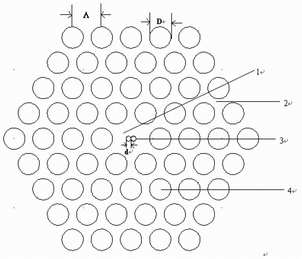
[0020] A photonic crystal fiber with high birefringence and low confinement loss, with a cross-sectional structure such as figure 1 shown, including core and cladding. The cladding of the optical fiber is consistent with that of ordinary photonic crystal fibers, which is the peripheral area formed by circular air holes (4) that surround the core (1) uniformly, have the same structure, and have a diameter of D. The refractive index of the cladding is lower than In the fiber core (1), the air holes (4) are arranged periodically in the background material, and each adjacent three air hole (4) units form an equilateral triangle on the optical fiber cross section. The fiber core (1) of the optical fiber is a high-refractive index core region composed of a background material (2) located in the center of the optical fiber and two small circular air holes (3) with a diameter of d. The air hole (3) is circumscribed in the background material (2). The material of the fiber core (1) i...

Embodiment 2

[0028] A high birefringence photonic crystal fiber structure, the background material (2) is selected as a polymer material, the diameter of the cladding air hole (4) is D=1.54μm, and the diameter of the two small circular air holes (3) at the core is d =0.426μm, the pitch of air holes Λ=2.11μm.


PUM


Abstract

A high-birefringence photonic crystal optical fiber low in limit and loss comprises a fiber core and a cladding. The cladding is a peripheral area formed by identical-structure circular air holes uniformly distributed around the fiber core. The air holes are arranged in optical fiber background materials periodically, and every three adjacent air holes form a right triangle. The fiber core is formed by background materials arranged at the center and two small circular air holes, and the two small circular air holes are externally tangent to each other and are equal in diameter. By changing the structure of the fiber core, high birefringence can be introduced by adjusting the diameter of the two small circular air holes within a certain range, and meanwhile, the optical fiber has quite low limit loss and is smooth in chromatic dispersion within a certain wavelength range. The high-birefringence photonic crystal optical fiber (PCF) in the above structure is simple in structure, has the advantages of high birefringence, low limit loss and smooth chromatic dispersion, and can be used for manufacturing polarization maintaining optical fiber with proper chromatic dispersion or polarization characteristics, and relevant optical fiber devices.

Description

technical field [0001] The invention belongs to the field of optical fiber technology, in particular to a photonic crystal optical fiber. Background technique [0002] In an ideal situation, a single-mode fiber transmits two mutually orthogonal modes, which have the same propagation constant and are degenerate with each other, so they can be regarded as a single polarization electric vector. However, the actual optical fiber is somewhat imperfect, and the internal refractive index distribution is also uneven due to the uneven internal stress. This causes the change of the propagation constants of the two fundamental modes, which leads to the disturbance of the polarization state of the fundamental mode in the single-mode fiber, destroys the mutual degeneracy of the fundamental modes, and thus causes the mode birefringence. The polarization-maintaining fiber artificially introduces geometric anisotropy in the cross-section of the fiber, which reduces the coupling coefficient...

Claims


Application Information

Patent Timeline
Patent Type & Authority Applications(China)
IPC IPC(8): G02B6/024G02B6/02
Inventor 曹晔李荣敏童峥嵘
Owner TIANJIN UNIVERSITY OF TECHNOLOGY
Why Eureka
Try Eureka