
Method for modeling control object in cooling process of central air conditioner

A technology for controlling objects and central air-conditioning, which is applied in the direction of adaptive control, general control system, control/regulation system, etc., and can solve the problems that lag time cannot be measured, variables cannot be measured, and lag time cannot be automatically identified.

Inactive Publication Date: 2013-01-09
SHANGHAI DAXI ENERGY TECH
View PDF0 Cites 7 Cited by
  • Summary
  • Abstract
  • Description
  • Claims
  • Application Information

AI Technical Summary

Problems solved by technology

In many industrial production processes, most of the pure lag time is caused by material transmission, which can be obtained by approximate estimation. For discrete time models, the pure lag time is generally taken as an integer multiple of the sampling time, but in the actual cooling process , some process variables cannot be measured, which leads to the fact that the lag time cannot be measured either
In order to obtain the lag time of the system, it is necessary to construct the lag time constant in the identification matrix equation, but the current conventional method cannot automatically identify the lag time
[0006] 4) Although the step response curve is a simple and easy method to measure the dynamic characteristics of the process, when the process is under the action of a large interference signal for a long time, the range of variation of the output of the controlled quantity may exceed the range allowed by the actual process. This makes the modeled step response curve an incomplete curve that does not go into steady state, so this situation cannot be modeled using the conventional soaring curve method

Method used


Image

  • Method for modeling control object in cooling process of central air conditioner
  • Method for modeling control object in cooling process of central air conditioner
  • Method for modeling control object in cooling process of central air conditioner

Examples


Embodiment Construction

[0046] The embodiments of the present invention will be further described in detail below in conjunction with the accompanying drawings, but the present embodiments are not intended to limit the present invention, and any similar structures and similar changes of the present invention should be included in the protection scope of the present invention.

[0047] A method for modeling a central air-conditioning cooling process control object provided by an embodiment of the present invention is characterized in that the specific steps are as follows:

[0048]1) Take the chilled water return temperature of the central air-conditioning as the output of the control object, and the chilled water supply temperature of the chiller as the input of the control object, so that the input of the control object of the central air-conditioning changes in a pulse manner multiple times, and measure each time The output pulse response value of the control object after the input quantity of the c...


PUM


Abstract

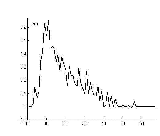
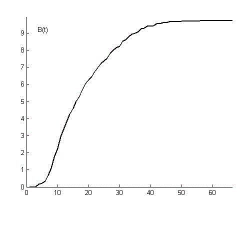
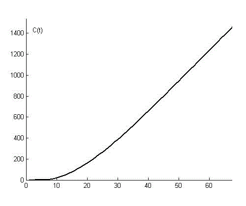
The invention provides a method for modeling a control object in a cooling process of a central air conditioner, relating to the field of cooling control technologies. The method has the advantages that the modeling accuracy and interference resistance are improved. According to the method, a pulse response curve of the control object is obtained firstly in a measurement manner, a step response curve and a ramp response curve are then obtained, a difference equation is written according to a measurement sample, the proportionality constant, time constant and lag time constant of the control object are obtained by using a least square method, a typical second-order plus lag object model is combined so as to obtain a pulse transfer function, and a difference equation of a control object model is further obtained. According to the method provided by the invention, the requirements for experimental conditions and site environments are low, the method has a filter action, the interference resistance is stronger, the modeling accuracy and reliability are high, and the modeling accuracy can be increased to be less than 3% from 7% compared with that of the conventional ascending curve method.

Description

technical field [0001] The invention relates to cooling control technology, in particular to a modeling method for a central air-conditioning cooling process control object. Background technique [0002] The energy consumption of air-conditioning and heating in my country accounts for 27% of the energy consumption of the whole society. At present, most of the operation and management of air-conditioning systems remain in a manual and semi-automatic state. Starting from the purpose of energy saving, it is extremely important to improve the urban air-conditioning and refrigeration system and realize the energy-saving control of the air-conditioning system. In the field of building energy saving and emission reduction, to design or transform the air conditioning control system, it is first necessary to determine the mathematical model of the dynamic characteristics of the control system, but the existing modeling methods for the control object of the air conditioning and coolin...

Claims


Application Information

Patent Timeline
Patent Type & Authority Applications(China)
IPC IPC(8): G05B13/04
Inventor 李爱国陈烈
Owner SHANGHAI DAXI ENERGY TECH
Learn More