Electric fuse ignition device, electric detonator comprising electric fuse ignition device, electronic detonator comprising electric fuse ignition device, and manufacturing methods for electric detonator and electronic detonator

An ignition device and electronic detonator technology, applied in fuzes, weapon accessories, offensive equipment, etc., can solve the problems of high cost, poor welding accuracy, bridge wire breakage, etc., and achieve simple manufacturing process, precise detonation accuracy, and high resistance value accuracy Effect

Inactive Publication Date: 2013-01-16
XINJIANG CHUANGANDA ELECTRONICS TECH DEV
View PDF7 Cites 22 Cited by
  • Summary
  • Abstract
  • Description
  • Claims
  • Application Information

AI Technical Summary

Problems solved by technology

[0004] The disadvantages of the above-mentioned traditional electric detonators and electronic detonators are: 1) the manufacturing process of the bridge wire is complicated, the yield rate is low, and the cost is high; On the pad, this will cause the bridge wire to break, which will increase the rejection rate of such electric detonators and electronic detonators; 3) The poor welding accuracy of manual secondary welding will introduce contact resistance, which is not conducive to accurate blasting

Method used


Image

  • Electric fuse ignition device, electric detonator comprising electric fuse ignition device, electronic detonator comprising electric fuse ignition device, and manufacturing methods for electric detonator and electronic detonator
  • Electric fuse ignition device, electric detonator comprising electric fuse ignition device, electronic detonator comprising electric fuse ignition device, and manufacturing methods for electric detonator and electronic detonator
  • Electric fuse ignition device, electric detonator comprising electric fuse ignition device, electronic detonator comprising electric fuse ignition device, and manufacturing methods for electric detonator and electronic detonator

Examples


Embodiment Construction

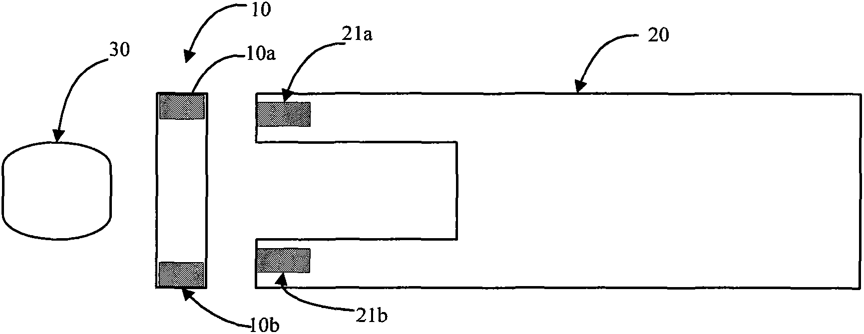
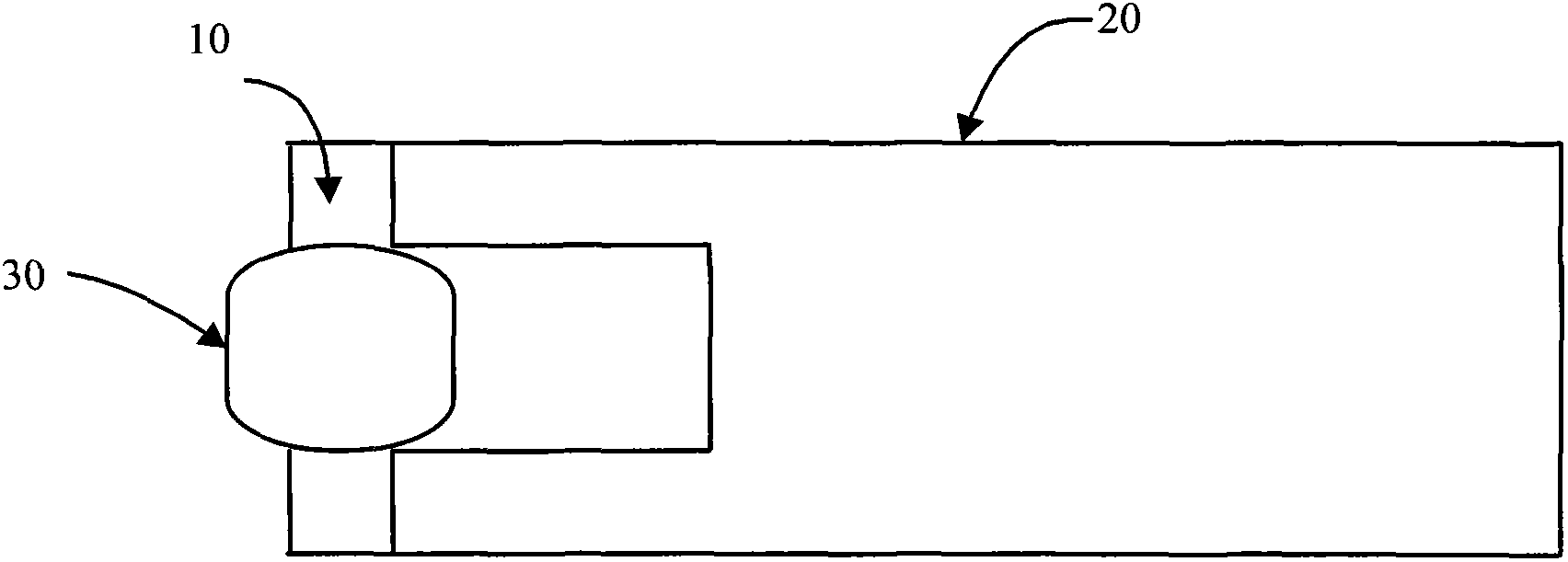
[0044] Figure 1-2 The following descriptions describe specific embodiments of the invention to teach those skilled in the art how to make and use the best mode of the invention. In order to teach inventive principles, some conventional aspects have been simplified or omitted. Those skilled in the art will appreciate that variations from these embodiments will fall within the scope of the invention. Those skilled in the art will appreciate that the features described below can be combined in various ways to form multiple variations of the invention. As a result, the invention is not limited to the specific embodiments described below, but only by the claims and their equivalents.

[0045] figure 1 The electrical fuze firing device according to the invention is shown disassembled. figure 2 An integrated electrical fuze firing device according to the invention is shown. Such as figure 1 with 2 As shown, the electric fuze ignition device according to the present invention...


PUM


Abstract

The invention provides an electric fuse ignition device. The electric fuse ignition device comprises a film resistor and an ignition explosive head wrapping the film resistor, wherein a power supply device can supply energy to the film resistor so that the film resistor generates enough joule heat and heats the ignition explosive head to a set temperature; and therefore, the ignition explosive head is lighted. The invention also provides an electric detonator comprising the electric fuse ignition device and an electronic detonator comprising the electric fuse ignition device. The invention also provides manufacturing methods for the electric detonator and the electronic detonator. According to the electric fuse ignition device provided by the invention, the film resistor is easy to manufacture, low in cost, high in yield, not easy to break and high in resistance precision, so that the electric detonator comprising the electric fuse ignition device and the electronic detonator comprising the electric fuse ignition device also have the advantages that the manufacturing is simple, the cost is low, the yield is high, the misfire rate is low, and the explosion precision is high. The manufacturing methods for the electric detonator and the electronic detonator are high in assembly automation degree, precise, reliable, high in yield and low in cost.

Description

【Technical field】 [0001] The invention relates to an electric fuze ignition device, an electric detonator including the same, an electronic detonator and a manufacturing method thereof, in particular to a film resistance electric fuze ignition device, an electric detonator including the same, an electronic detonator and a manufacturing method thereof. 【Background technique】 [0002] The detonator is a device that ignites the ignition charge by the fuze ignition device and then detonates various explosives. The detonator was invented by Nobel in 1865. Nobel discovered that putting mercury fulminate in a small tube formed a detonator, which could be used to detonate nitroglycerin absorbed by diatomaceous earth. [0003] With the development of detonator technology, electric detonators and electronic detonators appeared. Traditional electronic detonators and electric detonators generally utilize bridge wires and igniting powder as fuze ignition devices. This type of electric...

Claims


Application Information

Patent Timeline
Patent Type & Authority Applications(China)
IPC IPC(8): F42D1/045F42C19/12
Inventor 杨劲军罗军赵继鹏王齐亚张丽王安江龙建华黄小兵
Owner XINJIANG CHUANGANDA ELECTRONICS TECH DEV
Why Eureka
Try Eureka