
Low-power-consumption high-reliability electrification resetting circuit

A technology of electrical reset and reliability, applied in the direction of electrical components, electronic switches, pulse technology, etc., can solve the problems of increasing chip cost, unfavorable CMOS integration, etc., to achieve enhanced ability to resist power supply noise, reduce chip area, and ensure reliability sexual effect

Inactive Publication Date: 2013-01-16
UNIV OF ELECTRONICS SCI & TECH OF CHINA
View PDF4 Cites 34 Cited by
  • Summary
  • Abstract
  • Description
  • Claims
  • Application Information

AI Technical Summary

Problems solved by technology

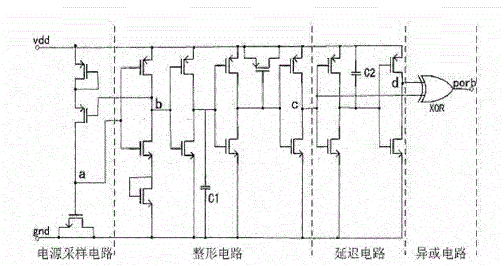
Its patent adopts the inverter and capacitor C2 composed of NMOS tube and PMOS tube as the delay unit. Even if the inverter is designed with an inverting tube, it still needs a capacitor C2 with a large enough area to ensure the reliability of the power-on reset circuit. The large capacitor C2 is not conducive to the integration of CMOS, which increases the cost of the chip. Its circuit is as follows: figure 1 shown

Method used


Image

  • Low-power-consumption high-reliability electrification resetting circuit
  • Low-power-consumption high-reliability electrification resetting circuit
  • Low-power-consumption high-reliability electrification resetting circuit

Examples


Embodiment Construction

[0026] specific implementation plan

[0027] The present invention is further described in detail through the embodiments in conjunction with the accompanying drawings

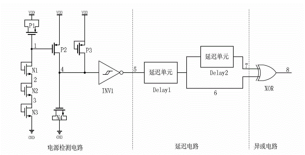
[0028] A low-power and high-reliability power-on reset circuit of the present invention is composed of a power detection circuit, a delay circuit and an XOR circuit, as shown in the attached figure 2 shown. Its specific circuit structure is as follows:

[0029] It is explained here that PMOS transistors and NMOS transistors are indicated by pipe P and pipe N respectively in the following documents and drawings, and the arrangement numbers of pipe P and pipe N are represented by numbers, such as the first PMOS transistor P1, the second PMOS transistor P2, the second PMOS transistor P2, An NMOS transistor N1, a second NMOS transistor N2, etc. are arranged in sequence.

[0030] The power detection circuit includes a PMOS transistor P1, a transistor P2, a transistor P3, an NMOS transistor N1, a transistor N2, ...


PUM


Abstract

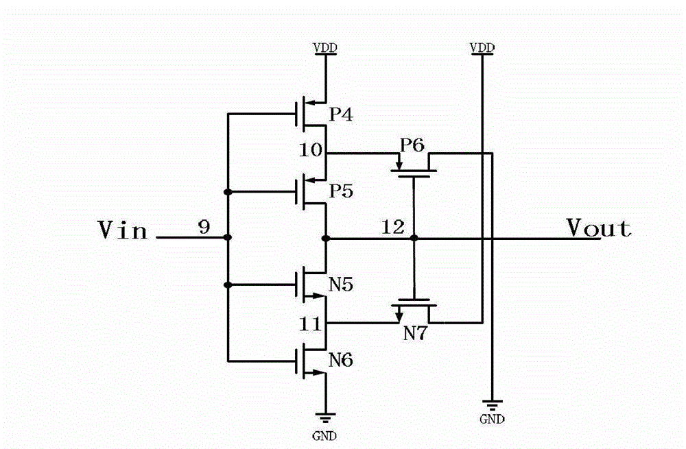
The invention discloses a low-power-consumption high-reliability electrification resetting circuit, and belongs to the field of integrated circuits. The low-power-consumption high-reliability electrification resetting circuit consists of a power supply detection circuit, a delay circuit and an exclusive OR circuit. A novel delay unit is used in the delay circuit, under the condition of not using the traditional large capacitor, the delay of hundreds of microseconds can be achieved, the area of a chip is effectively reduced, and the reliability of the chip is improved. The circuit has a full metal oxide semiconductor (MOS) tube structure, power supply noise is resisted by a phase inverter with a Schmidt function, and the static power consumption of the circuit is substantially zero after the circuit is reset.

Description

technical field [0001] The invention relates to a power-on reset circuit, which belongs to the field of integrated circuits. Background technique [0002] The power-on reset circuit controls the chip to enter the initial working state by detecting the change of the power supply voltage. When the power supply voltage rises from zero voltage to the normal working voltage, the power-on reset circuit will generate a power-on reset rectangular pulse to reset the chip, so that the entire chip circuit is ready to receive and process signals, and start to enter the normal working state. [0003] Whether the power-on reset rectangular pulse is effective for chip reset determines the reliability of the power-on reset circuit, and the power consumption and area of ​​the power-on reset circuit are also issues that need to be considered in the design. If the power supply voltage rises slowly and the power-on reset rectangular pulse appears, the power supply voltage of the entire chip is...

Claims


Application Information

Patent Timeline
Patent Type & Authority Applications(China)
IPC IPC(8): H03K17/22H03K17/28
Inventor 宁宁王成碧胡勇李天柱赵思源李华省吴霜毅
Owner UNIV OF ELECTRONICS SCI & TECH OF CHINA
Learn More