High-frequency alloy machine for silicon laminates

An alloy and high-frequency technology, applied in the field of silicon stack welding equipment, can solve the problems of difficult control of the overall height of the silicon stack, long heating cycle, large temperature difference between inside and outside, etc., and achieve good welding effect, uniform heating, and consistent size

Active Publication Date: 2013-01-23
江苏皋鑫电子有限公司
View PDF6 Cites 10 Cited by
  • Summary
  • Abstract
  • Description
  • Claims
  • Application Information

AI Technical Summary

Problems solved by technology

The disadvantages of this method are: the temperature is heated from the outside to the inside, and the temperature difference between the inside and outside i

Method used


Image

  • High-frequency alloy machine for silicon laminates
  • High-frequency alloy machine for silicon laminates
  • High-frequency alloy machine for silicon laminates

Examples


Embodiment Construction

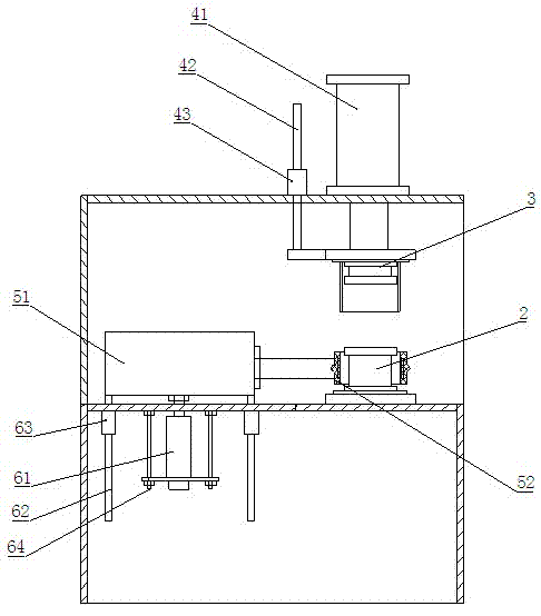
[0010] Such as figure 1 As shown, it includes frame 1, fixed worktable 2, movable worktable 3, movable worktable driving mechanism, high-frequency heater, high-frequency heating driving mechanism, and silicon stack height automatic detection system.

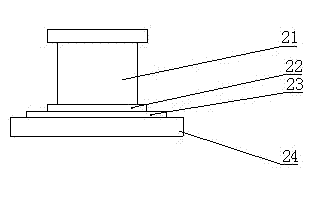
[0011] Fixed workbench 2 such as figure 2 As shown, it includes a lower graphite block 21, a lower heat insulating block 22, a lower magnetic resistance layer 23 and a lower base plate 24. The lower base plate 24 is fixed on the working platform in the middle of the frame 1, and the lower base plate 24 is installed sequentially from bottom to top. The magnetic resistance layer 23, the lower heat insulation block 22 and the lower graphite block 21 are all cylindrical, and the lower magnetic resistance layer 23 is a brass backing plate.

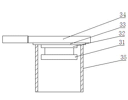
[0012] Movable workbench 3 is arranged on the top of fixed workbench, such as image 3 As shown, the movable workbench includes an upper graphite block 31, an upper heat insulation block 32, an...


PUM


Abstract

The invention relates to a high-frequency alloy machine for silicon laminates. The innovation point of the high-frequency alloy machine lies in comprising a rack, wherein a fixed work table is fixed on a work platform arranged at the middle part of the rack; a movable work table is arranged rightly above the fixed work table; a movable work table driving mechanism is used for driving the movable work table to be close to or far away from the fixed work table; the high-frequency heating coil axis of a high-frequency heater is coincided with the axis of the fixed work table and the movable work table; the high-frequency heater is driven by the high-frequency heating driving mechanism to lift and descend; and a silicon laminate height automatic detection system comprises a gridding ruler and a programmable logic controller. The high-frequency alloy machine has the advantages that the silicon laminates with welding flakes are clamped by the fixed work table and the movable worktable to be heated simultaneously inside and outside by the high-frequency heater placed outside the silicon laminates, the heating is uniform, the temperature difference is small, and the welding effect is good. The silicon laminate height automatic detection system is used for detecting the height changes of the silicon laminates; the programmable logic controller is used for controlling stopping heating and clamping, so that the overall heights of the silicon laminates are accurately controlled, and the sizes of the silicon laminates are consistent.

Description

technical field [0001] The invention relates to a silicon lamination welding equipment, in particular to a silicon lamination high-frequency alloy machine. Background technique [0002] After retrieving relevant documents, no technical solutions identical or similar to the content of the present invention have been found. When manufacturing silicon stacks, diode manufacturers set up silicon chips by overlapping them, and set soldering pieces between adjacent silicon chips, and then weld them into silicon chips. The traditional method uses electric furnace wire heating and welding. The disadvantages of this method are: the temperature is heated from the outside to the inside, and the temperature difference between the inside and the outside is large, the energy consumption is high, there is an open flame, the heating cycle is long, and the overall height of the silicon stack is difficult to control. Contents of the invention [0003] The technical problem to be solved by t...

Claims


Application Information

Patent Timeline
IPC IPC(8): B23K13/01
Inventor 刘训坚杨怀
Owner 江苏皋鑫电子有限公司
Why Eureka
Try Eureka