

Photoresist stripper composition
A technology of stripping agent and composition, applied in optics, photomechanical equipment, photosensitive material processing, etc., can solve the problems of manufacturing cost and time increase, and achieve excellent stripping effect
- Summary
- Abstract
- Description
- Claims
- Application Information
AI Technical Summary
Problems solved by technology
Method used
Image

Examples
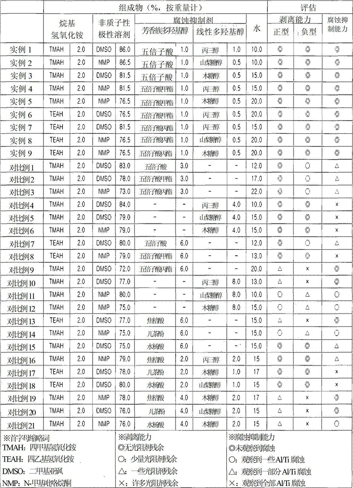
example 1 to 9 and comparative example 1 to 21
[0034] Compositions of Examples 1 to 9 and Comparative Examples 1 to 21 were prepared by mixing the components shown in Table 1.
[0035] Mixing is performed at room temperature for 1 hour or more to fully dissolve the solid corrosion inhibitor, then filtered through a Teflon filter.
experiment example
[0037] The stripping ability and corrosion inhibiting ability of the compositions obtained in Examples 1 to 9 and Comparative Examples 1 to 21 were evaluated as follows:
[0038] (1) Preparation of positive photoresist samples
[0039] Positive photoresist (THMR-iP 3300, TOK) is coated on a silicon wafer coated with silicon nitride, and then a photoresist pattern is formed through exposure and development processes. The pattern was transferred to the silicon nitride layer below the photoresist by dry etching to obtain a positive tone photoresist sample.
[0040] (2) Preparation of negative photoresist samples
[0041] A negative photoresist (PMER N-HC600, TOK) is coated on a silicon wafer, and then a photoresist pattern is formed through exposure, development and baking processes. Aluminum and titanium are sequentially spread on the silicon wafer to obtain a polished negative photoresist pattern.
PUM
 Abstract
Description
Claims
Application Information