Pre-buried elevating landfill gas collecting well

A lift-type, collection well technology, applied in landfill technology, solid waste removal, etc., can solve the problems of landfill gas escaping into the air, waste of people, money, and materials, buried, demolished, etc. Achieve the effects of simple structure, fast well completion speed and convenient construction

Inactive Publication Date: 2013-01-30
HENAN BCCY IND
View PDF8 Cites 7 Cited by
  • Summary
  • Abstract
  • Description
  • Claims
  • Application Information

AI Technical Summary

Problems solved by technology

[0004] At present, most waste-to-energy projects basically use shafts to collect landfill gas, but the shaft has a disadvantage. When the garbage in this layer reaches the specified height, the garbage needs to continue to be raised upwards. At present, the existing gas-gathering shafts are facing being destroyed. This will not only result in the waste of people, property, and materials, but also lead to a short period of blank time in the collection of landfill gas, which will cause a large amount of landfill gas to be directly dissipated into the air.

Method used


Image

  • Pre-buried elevating landfill gas collecting well

Examples


Embodiment 1

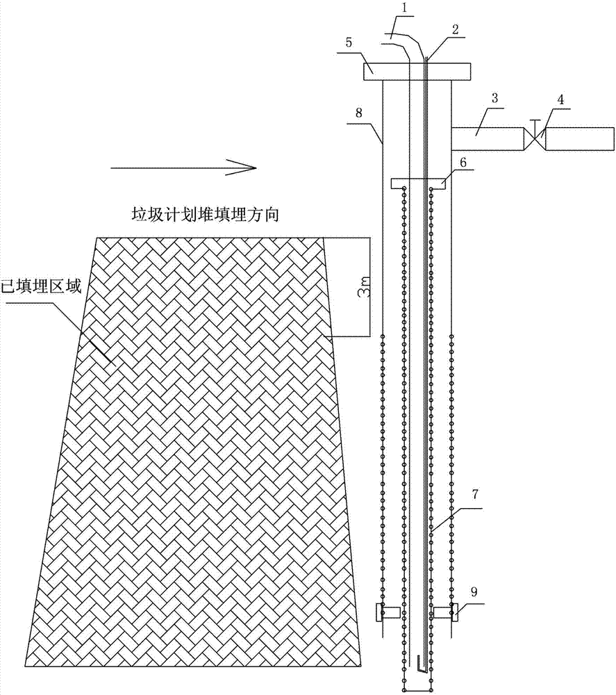
[0017] Embodiment one: see figure 1 , the pre-buried lifting type landfill gas collection well of the present invention includes a gas collection pipe and a gas extraction pipe. The gas collection pipe 3 is installed on the upper part of the gas collection pipe and is used to connect the gas extraction branch pipe for gas collection. The gas extraction pipe is provided with a wellhead valve 4. The wellhead valve is used to control the negative pressure and collection flow of the collection well. The gas collection pipe is composed of the gas collection outer pipe 8 and the gas collection inner flower pipe 7. The gas collection outer pipe 8 is composed of the upper gas collection external The solid pipe and the lower gas collection external flower tube are composed, and the gas collection internal flower tube 7 is arranged in the gas collection outer tube.

Embodiment 2

[0018] Embodiment two: see figure 1 , the pre-embedded lift-type landfill gas collection well of this embodiment is different from Embodiment 1 in that it contains a high-pressure drain pipe 1 and a high-pressure air intake pipe 2, and the high-pressure drain pipe 1 and high-pressure air intake pipe 2 are connected from the upper part of the gas collection pipe. Lift the well head 5 into and extend into the bottom of the gas collection internal flower tube 7, and the high-pressure air inlet pipe 2 is placed at the bottom of the high-pressure drain pipe 1 to discharge the leachate in the gas-collecting well by using air pressure.

Embodiment 3

[0019] Embodiment three: see figure 1 , the pre-embedded lift-type landfill gas collection well of this embodiment is different from Embodiment 1 or Embodiment 2 in that: a lifting flange head 6 is provided at the upper end of the flower tube 7 inside the gas collection, The lower end of the outer flower tube is equipped with 3-6 pieces of lifting bolts 9 apart from the bottom 20-30cm. The length of the lifting bolts 9 is preferably 2-3cm from the outer wall of the gas collection inner flower tube at its end.


PUM


Abstract

The invention relates to a landfill gas collecting well which is used for collection of garbage landfill gas. A pre-buried elevating landfill gas collecting well provided by the invention comprises a gas collection pipe and an exhaust pipe, wherein the exhaust pipe is installed at the upper part of the gas collection pipe and is used for connecting a branch exhaust pipe to realize gas collection, a well mouth valve is arranged on the exhaust pipe and is used for controlling negative pressure and collection flow of the landfill gas collecting well, the gas collection pipe is composed of an outer gas collection pipe and an inner gas collection floral pipe, the outer gas collection pipe is composed of an outer gas collection solid pipe at an upper part and an outer gas collection floral pipe at a lower part, and the inner gas collection floral pipe is arranged in the outer gas collection pipe. According to the invention, the pre-buried elevating landfill gas collecting well has a simple structure and reasonable design, the characteristics of a simple process, convenient construction, a fast well forming speed, a mature construction process, strong environmental adaptability and a good gas collection effect are obtained, and low cost and economic benefits are achieved.

Description

technical field [0001] The invention relates to a landfill gas collection well, in particular to a pre-buried lift-type landfill gas collection well for collecting landfill gas from garbage. Background technique [0002] Landfill gas refers to the gas generated by microbial anaerobic digestion and degradation of a large amount of organic matter contained in the accumulated or landfilled municipal solid waste during the landfill process. Landfill gas is a kind of mixed gas. Its generation and release are determined by the components of the garbage, the moisture status of the garbage dump, the temperature of the garbage, the pH value, the meteorological conditions, the age of the garbage, the structure of the garbage dump, and the environmental geology and other conditions. . [0003] Under normal circumstances, landfill gas can be released in many ways: on the one hand, it can diffuse to the atmosphere through the surface of the landfill; Horizontal and horizontal migration...

Claims


Application Information

Patent Timeline
Patent Type & Authority Applications(China)
IPC IPC(8): B09B1/00
CPCY02W30/30
Inventor 吕运之张松元张向兵
Owner HENAN BCCY IND
Why Eureka
Try Eureka