High speed railway based aerodynamic aerotrain with simulated wings

An aerodynamic levitation, high-speed railway technology, applied in the field of locomotives and carriages, can solve problems such as waste of resources, inability to change tracks of trains, health, ecological environment balance, and adverse effects of electronic products, and achieve the effect of reducing pressure and simple structure

Active Publication Date: 2013-01-30
BEIHANG UNIV
View PDF7 Cites 16 Cited by
  • Summary
  • Abstract
  • Description
  • Claims
  • Application Information

AI Technical Summary

Problems solved by technology

[0002] At present, the known means of speeding up trains based on high-speed railways is to use magnetic levitation to reduce the friction of the wheels on the rails. However, the disadvantages of the magnetic levitation method are: 1. The train cannot change tracks, unlike trains that run on conventional railways. Turnouts pass from one rail to another; one track can only accommodate one train running back and forth, resulting in a waste of resources
2. Since the maglev system relies on electromagnetic force for levitation, guidance and driving operation, once the power is cut off, the maglev train will have serious safety accidents, so the safety guarantee measures for the maglev train after the power failure have not been completely resolved
3. Strong magnetic fields will have adverse effects on human health, the balance of the ecological environment and the operation of electronic products

Method used


Image

  • High speed railway based aerodynamic aerotrain with simulated wings
  • High speed railway based aerodynamic aerotrain with simulated wings
  • High speed railway based aerodynamic aerotrain with simulated wings

Examples


Embodiment 1

[0039] See Figure 4 and Figure 5 , the structure of the imitation wing is mainly composed of the uppermost horizontal wing 1, the vertical wing 4 of the middle part and the lowermost rotatable base that can rotate 360 ​​degrees; wherein, the rotatable base is a double layer with a diameter of 1 meter. The structure of discs stacked, the thickness of the lower disc 8 of the rotatable base is 25 mm, the thickness of the upper disc 6 of the rotatable base is 65 mm, the upper disc is connected with the lower disc through the rotating shaft 7, and The rotation axis passes through the centers of the two disks; the upper disk can rotate 360 ​​degrees along with the rotation axis. The lower edge of the vertical wing is connected to the central symmetry axis of the upper surface of the upper disk of the rotatable base, and the vertical wing and the rotatable base are at a right angle of 90 degrees; the upper edge of the vertical wing is connected to the It is connected at the cente...

Embodiment 2

[0054] The structure of imitation wing is basically the same as embodiment 1, and the difference is:

[0055] The thickness of the lower disc of the rotatable base is 20 mm, and the thickness of the upper disc of the rotatable base is 60 mm.

[0056] The wing height of the described vertical wing is 70 centimeters, the root-to-shoot ratio is 1, the area is 1.05 square meters (including the vertical wing swing), the leading edge sweep angle is 0 degree, and the trailing edge is vertical.

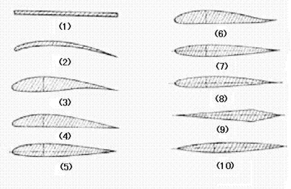
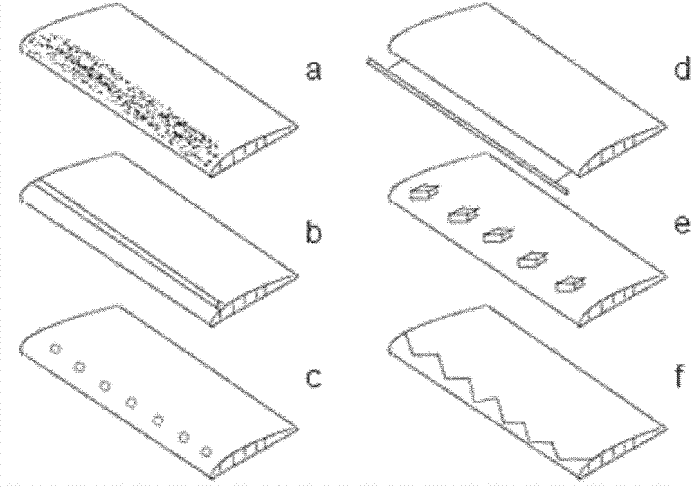
[0057] Described horizontal wing adopts flat wing, and the section of its flat wing is as follows figure 1 Shown in (1), the artificial spoiler structure added near the leading edge part of the upper surface of the horizontal wing is a zigzag protruding spoiler (such as figure 2 shown in f).

[0058] The area of ​​described horizontal wing is 4.5 square meters, and this moment root tip ratio is 1, and the length of horizontal wing is 450 centimetres, and leading edge sweep angle is 0 degr...

Embodiment 3

[0070] The structure of imitation wing is basically the same as embodiment 1, and the difference is:

[0071] The thickness of the lower disc of the rotatable base is 20 mm, and the thickness of the upper disc of the rotatable base is 60 mm.

[0072] The wing height of the described vertical wing is 50 centimeters, the root-to-shoot ratio is 0.5, the area is 0.5 square meters (including the vertical wing swing), the leading edge sweep angle is 26.50 degrees, and the trailing edge is vertical.

[0073] Described horizontal wing adopts flat wing, and the section of its flat wing is as follows figure 1 Shown in (1), the artificial flow disturbance structure added near the leading edge part of the upper surface of the horizontal wing is to add an elastic flow-around band (such as figure 2 shown in d).

[0074] The area of ​​described horizontal wing is 2.25 square meters, and this moment root tip ratio is 0.3, and the length of horizontal wing is 300 centimetres, and leading e...


PUM


Abstract

The invention relates to a locomotive and coaches in a railway system, in particular to a high speed railway based aerodynamic aerotrain applying aerodynamics and provided with simulated wings. The simulated wings simulating a wing structure of an airplane are mounted on the top portion of each locomotive and each coach of a train. During traveling, due to the simulated wings mounted on the train, airflow moving relative to the train acts on the simulated wings to generate uplifting force, the uplifting force can be applied to the train traveling at high speed, so that pressure on a rail from the train is reduced, and since the force is generated by aerodynamic force, no extra energy is consumed, and no pollution is caused. Via relative motion to the train, the airflow can act on the simulated wings to generate the uplifting force, so that pressure on the rail from the train is reduced. The simulated wings are simple in structure.

Description

technical field [0001] The present invention relates to locomotives and carriages in the railway system, and in particular to the use of aerodynamics to generate a certain degree of air suspension force for high-speed trains through the imitation wing structure imitating the wing structure of an airplane installed on the train An aerodynamic levitation train with imitation wings based on high-speed rail. Background technique [0002] At present, the known means of speeding up trains based on high-speed railways is to use magnetic levitation to reduce the friction of the wheels on the rails. However, the disadvantages of the magnetic levitation method are: 1. The train cannot change tracks, unlike trains that run on conventional railways. Turnouts enter from one rail to another; one track can only accommodate one train to and fro, resulting in a waste of resources. 2. Since the maglev system relies on electromagnetic force for levitation, guidance and driving operation, once...

Claims


Application Information

Patent Timeline
Patent Type & Authority Applications(China)
IPC IPC(8): B61D17/02B61B13/08
CPCY02T30/32Y02T30/00
Inventor 江雷刘流马洋查金龙刘克松
Owner BEIHANG UNIV
Why Eureka
Try Eureka