
Current predictive control method of permanent magnet synchronous motor

A technology of permanent magnet synchronous motor and current prediction, which is applied in the field of permanent magnet synchronous motor current prediction control and permanent magnet synchronous motor, and can solve the problems of slow dynamic response speed, steady state static error, etc.

Inactive Publication Date: 2013-01-30
EAST CHINA ARCHITECTURAL DESIGN & RES INST
View PDF4 Cites 78 Cited by
  • Summary
  • Abstract
  • Description
  • Claims
  • Application Information

AI Technical Summary

Problems solved by technology

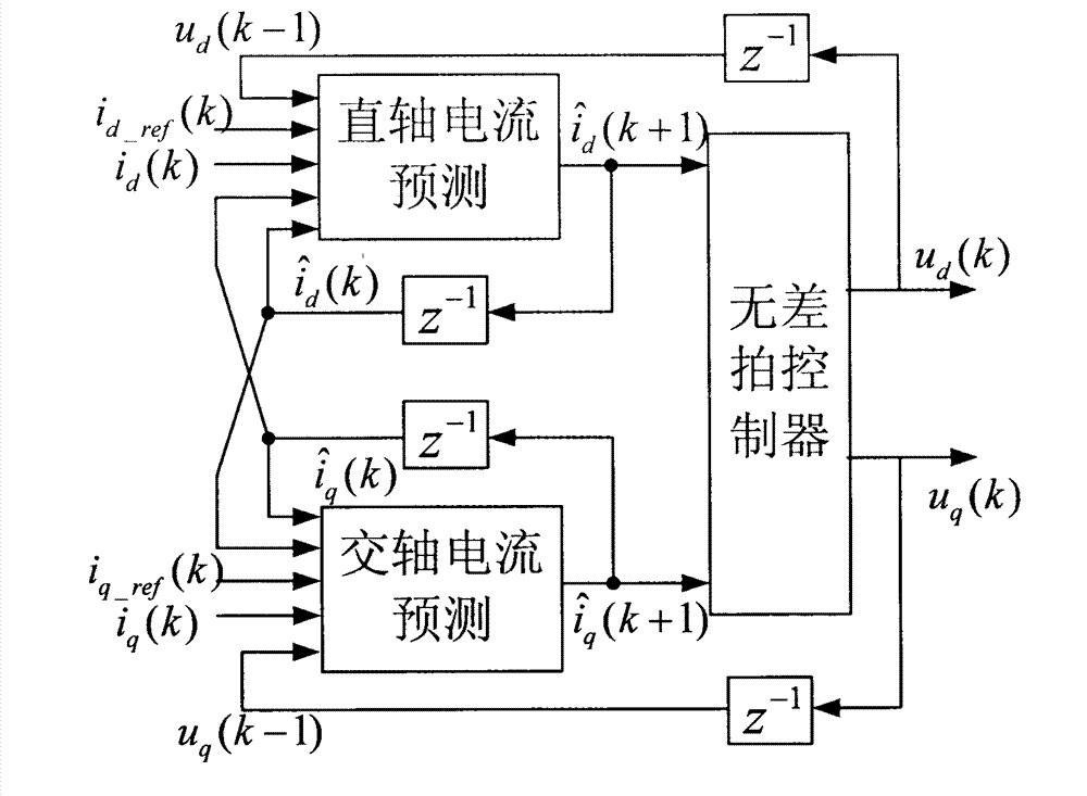
[0008] Therefore, in order to speed up the dynamic response speed of the permanent magnet synchronous motor, improve the control accuracy, and improve the problems of slow dynamic response speed and steady-state static error of the existing PID controller, it is necessary to design a current predictive control method for the permanent magnet synchronous motor. For permanent magnet synchronous motors, deadbeat control is adopted for the stator current to improve control speed and precision, and reduce torque ripple and noise

Method used


Image

  • Current predictive control method of permanent magnet synchronous motor
  • Current predictive control method of permanent magnet synchronous motor
  • Current predictive control method of permanent magnet synchronous motor

Examples


Embodiment Construction

[0067] In the following, an example inverter air conditioner compressor of the present invention will be described in detail with reference to the accompanying drawings. This example is implemented on the premise of the technical solution of the present invention, and a detailed implementation manner and process are given, but the implementation manner of the present invention is not limited to the following instance.

[0068] The main driving component in the inverter air conditioner system is the permanent magnet synchronous motor of the compressor. The present invention is a method for controlling the stator current of the permanent magnet synchronous motor, which is applicable to this type of air conditioner. Therefore, in the embodiment, only the stator current of the compressor is used. The control-related parts are introduced in detail, and other functional components of the air-conditioning system are not introduced.

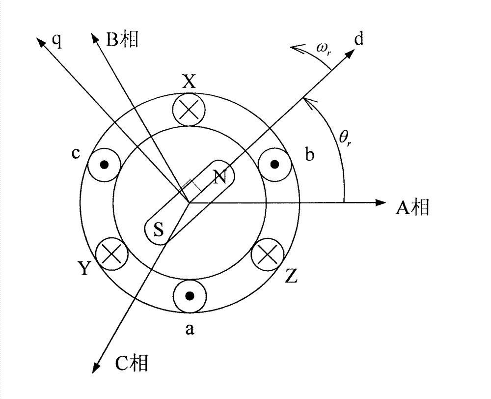
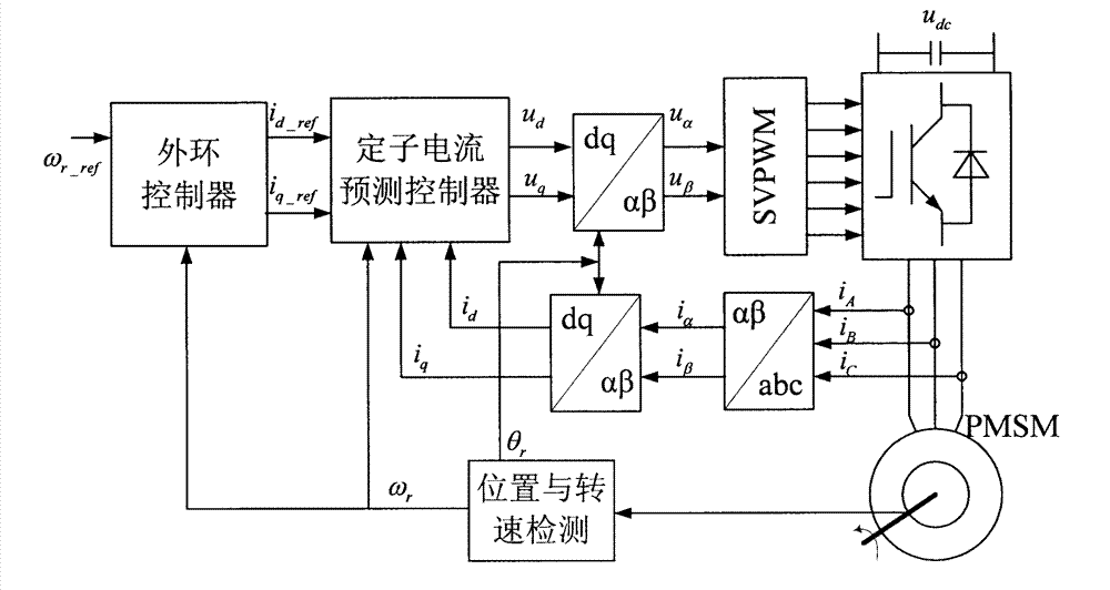
[0069] like figure 1 As shown in the schematic di...


PUM


Abstract

The invention relates to a current predictive control method of a permanent magnet synchronous motor, which belongs to the electric control field. The dynamic response speed and the control accuracy for the stator current control of the permanent magnet synchronous motor are improved through stator current prediction and deadbeat control, and the system delaying is compensated, so that the noise and the torque ripple of the motor in operation are reduced. The method comprises the steps as follows: obtaining a three phase stator current signal, and the electrical angle and the electrical angular speed of the motor rotor through the technologies of sensor sampling and a photoelectric coded disc or position sensorless detection; carrying out Clarke transformation and Park transformation on the stator current signal to obtain the stator current in a synchronous revolution dq coordinate system; substituting the obtained stator current signal in the dq coordinate system into a control equation of a current predictive controller of the permanent magnet synchronous motor, carrying out deadbeat control according to the given value of the obtained stator current in the dq coordinate system in an outer ring controller to obtain a stator voltage vector in the dq coordinate system; carrying out Park inverse transformation on the obtained stator voltage vector in the dq coordinate system, to obtain a pulse-width modulation (PWM) control signal of an inverter by a space vector pulse width modulation (SVPWM) method, controlling the stator current through the inverter, and then implementing the current predictive control over the permanent magnet synchronous motor.

Description

technical field [0001] The invention relates to a current prediction control method of a permanent magnet synchronous motor, in particular to a permanent magnet synchronous motor used in variable frequency air conditioners, which is applicable to all permanent magnet synchronous motor models, and belongs to the field of electrical control. Background technique [0002] With the development of the permanent magnet material industry, permanent magnet synchronous motors have been widely used. Compared with asynchronous motors, permanent magnet synchronous motors have the advantages of high efficiency, high air-gap magnetic field density, and high power factor. Permanent magnet synchronous motor is mainly divided into two categories according to the induced electromotive force: permanent magnet synchronous motor (PMSM) and brushless DC motor (BLDCM). BLDCM has low cost, simple detection device and control, and large output torque. Under the condition of the same volume, BLDCM ha...

Claims


Application Information

Patent Timeline
IPC IPC(8): H02P21/14H02P21/22H02P27/08
Inventor 景卉
Owner EAST CHINA ARCHITECTURAL DESIGN & RES INST
Learn More