Gas-liquid membrane contactor and mixed gas separation method using same

A gas-liquid membrane contactor and liquid technology, applied in the field of membrane separation, can solve the problems of difficult assembly, unstable mass transfer efficiency and high cost, achieve convenient assembly and cleaning, avoid uneven distribution density of hollow fibers, and compact device structure Effect

Inactive Publication Date: 2013-02-06
NANJING UNIV OF INFORMATION SCI & TECH
View PDF5 Cites 8 Cited by
  • Summary
  • Abstract
  • Description
  • Claims
  • Application Information

AI Technical Summary

Problems solved by technology

[0005] The purpose of the present invention is to provide a gas-liquid membrane contactor and a mixed gas separation method using it to

Method used


Image

  • Gas-liquid membrane contactor and mixed gas separation method using same
  • Gas-liquid membrane contactor and mixed gas separation method using same
  • Gas-liquid membrane contactor and mixed gas separation method using same

Examples


Embodiment 1

[0041] Example 1 Description of the structure of the gas-liquid film contactor

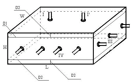
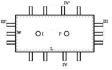
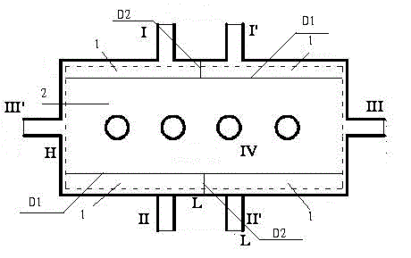
[0042] like Figure 1 to Figure 8 As shown, a multi-channel gas-liquid film contactor, including a rectangular frame such as figure 1 In the rectangular parallelepiped structure, the air cavity plate fixed between the upper and lower surfaces of the frame is shown as a D1 laminate in the figure, and the air cavity plate - D1 divides the inner cavity of the frame into an air cavity 1 and a liquid cavity 2; The top surface of the air chamber 1 is provided with gas interfaces I and I' in pairs on the same side, and the opposite outer surface of the liquid chamber 2 is provided with liquid interfaces III and III' in pairs, and another air chamber plate D2 is also included. Chamber 1 is divided into two separate sub-air chambers, and the paired gas ports communicate with different sub-air chambers respectively, that is to say, gas port I communicates with the left sub-air chamber, and gas port I' comm...

Embodiment 2

[0047] According to different separation situations, select different cuboid sizes and match them with hollow fiber membranes of suitable materials, set the interval and effective length, that is, the horizontal length, according to the preferred separation method, and conduct tests.

example 2-1

[0049] refer to figure 1 As shown in -8, a multi-channel gas-liquid membrane contactor for separating mixed gases, its structure: L = 100 cm, W = 15 cm, H = 10 cm, air cavity D = 1.25 cm, hollow fiber PP membrane wire arrangement The interval is 0.5cm, and the effective length of the shortest membrane filament is 50%L.

[0050] Operation process: gas mixture composition N 2 / CO 2 , pressure 0.1MPa, CO 2 Mole fraction 25%, flow rate 1.5L / min; liquid (absorbent) 30% MEA, flow rate 300mL / min. 1) The gas-liquid process is operated in parallel (I→I', II→II'); the liquid process III→III' forms a countercurrent flow with the gas. At this time, compared with the existing hollow fiber membrane contactor of the same scale, the fraction Efficiency increased by 28%. 2) The gas-liquid process is operated in parallel (I→I', II→II'); the liquid process III'→III forms a co-current flow with the gas. At this time, compared with the existing hollow fiber membrane contactor of the same scal...


PUM


Abstract

The invention relates to the technical field of membrane separation, in particular to a gas-liquid membrane contactor and a mixed gas separation method using the same and solves the problems of unstable mass-transfer efficiency, difficulty in assembling and high cost of existing gas-liquid membrane contactors. The gas-liquid membrane contactor is of a tube shell type rectangular structure consisting of a hollow fiber membrane and a frame. The hollow fiber membrane is a tube pass for delivering air, the rectangular frame is a shell pass for delivering liquid, fair current, countercurrent, cross current separation can be achieved selectively, and the shortages of uneven distribution density of hollow fibers and uneven shell pass liquid are effectively avoided. Therefore, the gas-liquid membrane contactor is better than existing hollow fiber membrane contactors, and the separation efficiency is improved by 20-38 percent.

Description

technical field [0001] The invention relates to the technical field of membrane separation, in particular to a gas-liquid membrane contactor and a mixed gas separation method using the same. Background technique [0002] Mixed gas includes various process gas streams and flue gases in industrial production, such as natural gas, synthetic gas, refinery gas, Claus tail gas, power plant tail gas and flue gas. These mixed gases contain various harmful impurity gases, the most common The impurity gas has H 2 S, SO 2 and CO 2 Such as acid gases and VOCs, before these gas streams are further processed or discharged, they must be purified to remove harmful impurity gases (such as acid gases and VOCs, etc.), so as to meet the requirements of subsequent stages or environmental protection emission standards. Membrane contactor is a new type of gas separation device, which has the advantages of stable mass transfer interface, high specific surface area, high mass transfer efficiency,...

Claims


Application Information

Patent Timeline
IPC IPC(8): B01D53/22B01D63/02
Inventor 陆建刚花爱春许正文承玲林凤英樊璠
Owner NANJING UNIV OF INFORMATION SCI & TECH
Why Eureka
Try Eureka