Steel ball gas removal system of pulverized coal boiler

A technology for steel ball ash removal and pulverized coal boilers, which is applied in the field of pulverized coal boilers. It can solve the problems of corroded steel balls, steel balls rusted into blocks, and low separation efficiency of separators, so as to remove cohesive ash, prevent steel balls from agglomerating, and separate high efficiency effect

Inactive Publication Date: 2013-02-06
TSINGHUA UNIV
View PDF6 Cites 11 Cited by
  • Summary
  • Abstract
  • Description
  • Claims
  • Application Information

AI Technical Summary

Problems solved by technology

[0004] There are three main problems in the existing steel ball ash removal system: first, the separation of steel balls and ash in the steel ball ash removal system for oil-fired boilers is achieved through a separator, the separation efficiency of the separator is low, and the reliability of the system is not high
The ash on the surface of the steel ball may contain sulfuric acid vapor or sulfuric acid, which will form dilute sulfuric acid under the influence of moisture in the atmosphere, corrode the steel ball, cause the steel ball to rust into blocks, and affect the normal operation of the ash removal system
In addition, during the falling process, due to the ejection effect of the heating surface or the wall of the ash hopper, the steel ball may be ejected into the flue gas outlet pipe, or due to unreasonable structural design, the steel ball will be carried by the flue gas into the flue gas outlet pipe, affecting subsequent equipment safe and reliable operation of

Method used


Image

  • Steel ball gas removal system of pulverized coal boiler
  • Steel ball gas removal system of pulverized coal boiler
  • Steel ball gas removal system of pulverized coal boiler

Examples


Embodiment Construction

[0014] The specific embodiments of the present invention will be further described below in conjunction with the accompanying drawings.

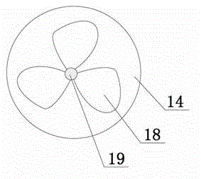
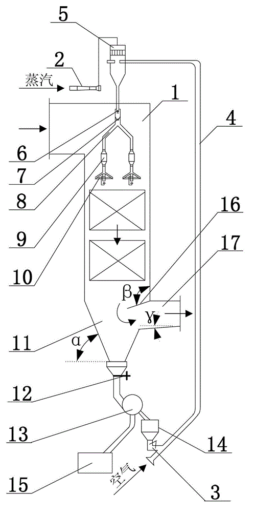
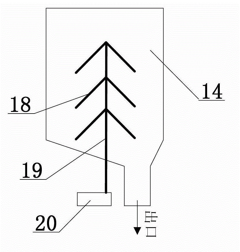
[0015] figure 1 It is a structural schematic diagram of a steel ball ash removal system for a coal-fired boiler provided by the present invention. As shown in the figure, the system includes a steam ejector 2 , a steel ball capture and spreading system, an air lock 12 , a steel ball separation and storage system, a bead feeder 3 and a steel ball delivery pipe 4 . The steel ball capture and dissemination system is arranged on the upper part of the boiler tail flue, including steel ball catcher 5, conical air locker 6, small bucket 7, distributor 8, buffer 9 and spreader 10. One end of the steel ball conveying pipe 4 is connected with the bead feeder 3 , and the other end is connected with the steel ball catcher 5 . Between the air locker 12 and the bead feeder 3, a magnetic separator 13 and a bead storage bucket 14 are sequentially arranged...


PUM


Abstract

The invention relates to a steel ball gas removal system of a pulverized coal boiler, belonging to a boiler tail flue gas removal device. The steel ball gas removal system comprises a steam ejector, a steel ball capture and spread system, a gas lock, a steel ball separation and storage system, a ball supplier and a steel ball conveying pipe, wherein a magnetic classifier and a ball storage bucket are sequentially arranged between the gas lock and the ball supplier; the magnetic classifier can used for realizing the effective separation of steel balls and ash, and the system reliability is good; the ball storage bucket is used for storing falling steel balls, and in order to prevent the steel balls from being corroded and caked, a rotating blade is arranged in the ball storage bucket; the intersection angle of the wall surface of the ash bucket and the horizontal plane is 45-60 degrees; and an adjustable baffle plate is arranged above an inlet part of a flue gas outlet pipe, and the lower part of the flue gas outlet pipe is inclined for 5-10 degrees towards the inner side of the ash bucket to prevent the steel balls from entering the flue gas outlet pipe along with gas flows. By adopting the steel ball gas removal system provided by the invention, cohesive ash deposits on a heating surface of a boiler tail flue can be effectively cleared away, and the stability and reliability of the system are good.

Description

technical field [0001] The invention relates to the ash removal technology for the tail flue of a pulverized coal boiler, in particular for the pulverized coal boiler with cohesive or serious ash accumulation on the heating surface of the tail flue. Background technique [0002] The ash in the heating area will not only reduce the heat transfer effect of the heating surface of the boiler, reduce the steam temperature, increase the exhaust gas temperature, and increase the heat loss of the exhaust gas, but also increase the flow resistance of the flue gas, increase the power consumption of the induced draft fan, and in severe cases will limit the output of the boiler. At present, pulverized coal boilers in power plants usually use steam soot blowing, and use high-speed steam jets to scour the heating surface to make the ash deposits on the heating surface fall off. When cohesive dust deposits or severe dust deposits appear on the heating surface of the tail flue, the effect ...

Claims


Application Information

Patent Timeline
Patent Type & Authority Applications(China)
IPC IPC(8): F23J3/02
Inventor 杨燕梅吕俊复张海吴玉新
Owner TSINGHUA UNIV
Why Eureka
Try Eureka