Debris-flow drainage canal with energy dissipation and drainage functions and application thereof

A technology for draining troughs and debris flows, which is applied in water conservancy projects, artificial waterways, buildings, etc. It can solve problems such as insufficient energy dissipation of V-shaped grooves, failure of the function of the drainage trough, failure of the bottom of the trough, etc., and achieve a good drainage effect Effect

Active Publication Date: 2013-02-13
INST OF MOUNTAIN HAZARDS & ENVIRONMENT CHINESE ACADEMY OF SCI
View PDF7 Cites 10 Cited by
  • Summary
  • Abstract
  • Description
  • Claims
  • Application Information

AI Technical Summary

Problems solved by technology

[0003] At present, the commonly used structural forms of debris flow drainage channels are Dongchuan trough (soft foundation energy dissipation trough) and V-shaped trough, but these two trough types have obvious deficiencies in practical engineering applications
Dongchuan Trough uses transverse ribs to block part of the debris flow, and eliminates most of its kinetic energy through strong stirring and mixing between the debris flow and the material of the ditch bed, thereby reducing the flow velocity during the discharge of the debris flow; but because the debris flow is moving downstream In the process, most of its energy has been reduced, and the flow rate has gradually decreased, resulting in the possibility of siltation, which in turn leads to the failure of the function of the drainage channel; defect
The V-shaped trough adopts the full lining method, which reduces the frictional resistance between the debris flow and the bottom of the trough, which is conducive to the speed-up of the debris flow in the process of advancing, so that the debris flow can pass through smoothly, so the phenomenon of sedimentation in the trough rarely occurs; however, due to the lack of necessary The large particles in the debris flow fluid have a strong abrasive effect on the drainage channel, which is easy to cause damage to the bottom of the channel; therefore, the V-shaped channel has insufficient energy dissipation and cannot be used for Defects with a slope greater than 20%

Method used


Image

  • Debris-flow drainage canal with energy dissipation and drainage functions and application thereof
  • Debris-flow drainage canal with energy dissipation and drainage functions and application thereof
  • Debris-flow drainage canal with energy dissipation and drainage functions and application thereof

Examples


Embodiment 1

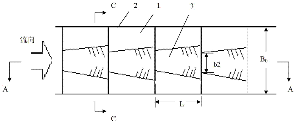
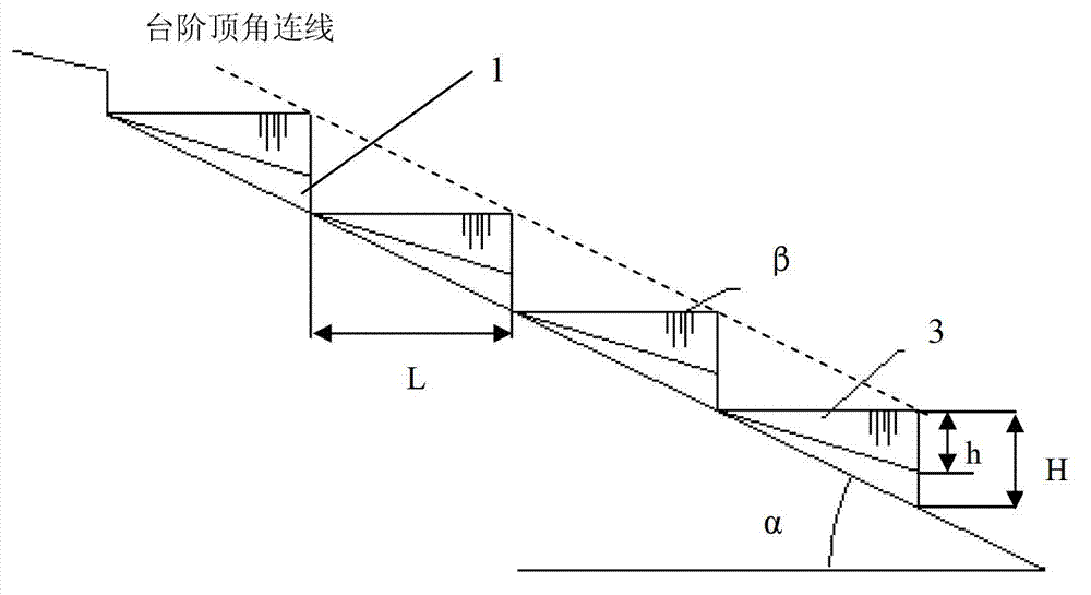
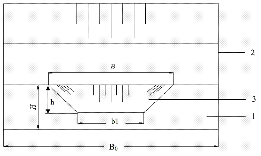
[0032] Such as figure 1 , figure 2 , image 3 , Figure 4 shown. For the basin area of ​​0.5km 2 , bulk density is 1700kg / m 3 , dilute debris flow with ditch-bed gradient of 25% (that is, slope α at the bottom of the ditch is equal to 25%), at P 2% Under the design standard, the flow rate of debris flow is 20m 3 / s, it is proposed to build a debris flow drainage channel along the debris flow channel with consideration of energy dissipation and drainage. The vertical height difference between the start and end of the guide trough is 48.0m, and the total length of the guide trough is 198.0m. Its structure includes a fully lined row guide trough bottom plate and the row guide trough side walls 2 on both sides. The row guide trough bottom plate is a ladder shape formed by continuous connection of 40 steps. The surface of the ditch bed is parallel; each step 1 is provided with a groove 3, which is symmetrical along the center line of the guide groove, and the width of the g...

Embodiment 2

[0035] Such as figure 1 , figure 2 , image 3 , Figure 4 shown. The same place as Embodiment 1 will not be repeated, and the difference is that the bulk density of debris flow is 1300kg / m 3 , in order to enhance the turbulence of the debris fluid and further improve the energy dissipation rate of the drainage channel, the height and length of the steps 1 in Embodiment 1 are reduced, and the number of steps 1 is increased. . The height H of the step 1 is 0.8m, the height h of the groove 3 on the vertical surface of the step 1 is 0.4m; the length L of the step 1 is 3.2m, and the length of the groove 3 on the top surface of the step 1 is 3.2m; The slope β of the top surface is 0.

Embodiment 3

[0037] Such as Figure 5 , Figure 6 , Figure 7 , Figure 8 shown. For a watershed area of ​​3.5km 2 , bulk density is 2200kg / m 3 , the viscous debris flow with a ditch-bed gradient of 8% (that is, the slope at the bottom of the ditch α is equal to 8%), at P 2% Under the design standard, the flow of debris flow is 60m 3 / s, it is proposed to build a debris flow drainage channel along the debris flow channel with consideration of energy dissipation and drainage. The vertical height difference between the start and end of the guide trough is 48.0m, and the total length of the guide trough is 602.0m. Its structure includes a fully-lined row guide trough bottom plate and the row guide trough side walls 2 on both sides. The row guide trough bottom plate is a ladder shape formed by continuous connection of 24 steps 1, and the connection line between the top corners of steps 1 at each level The surface of the ditch bed is parallel; each step 1 is provided with a groove 3, wh...


PUM


Abstract

The invention discloses a debris-flow drainage canal with energy dissipation and drainage functions and an application of the debris-flow drainage canal with energy dissipation and drainage functions. The drainage canal comprises a fully-lining drainage canal bottom plate and drainage canal side walls on two sides of the drainage canal bottom plate; the drainage canal bottom plate is in the shape of continuously-connected multiple-stage steps, the steps are provided with grooves; the width of the grooves on the top surfaces of the steps increases gradually along the flow direction of the debris flow, and the width of the grooves on the vertical surfaces of the steps decreases gradually; and the maximum width of the grooves on the top surfaces of the steps coincide with the maximum width B on the vertical surfaces of the steps. Compared wit the prior art, the step shape design is adopted to dissipate the energy of the debris flow all the way and the groove design is adopted to drain the debris flow, so the debris-flow drainage canal disclosed by the invention has high efficiency and good drainage capacity. By adjusting the height and the length of the steps and the size and the shape of grooves, the debris-flow drainagedrainage canal can be used for preventing the debris flow with any gradient and any nature.

Description

technical field [0001] The invention relates to a mud-rock flow prevention technology, in particular to a mud-rock flow drainage groove based on step energy dissipation and groove drainage, and its application in the case of any slope and any fluid property. Background technique [0002] my country is a mountainous country with complex terrain and geological conditions. The torrents and mudslides formed under some extreme climatic conditions have seriously affected the production and life of local people. Therefore, the prevention and control of debris flow is of great significance to protect the safety of people's lives and property and promote social and economic development. Debris flow drainage channel is an important project in debris flow prevention and control engineering. According to the topography and landform conditions of the local debris flow circulation area and combined with the characteristics of debris flow itself, many experts and scholars have proposed var...

Claims


Application Information

Patent Timeline
Patent Type & Authority Applications(China)
IPC IPC(8): E02B5/00
Inventor 陈华勇崔鹏周公旦朱兴华唐金波洪勇
Owner INST OF MOUNTAIN HAZARDS & ENVIRONMENT CHINESE ACADEMY OF SCI
Why Eureka
Try Eureka