A method for strengthening steel pipe joints with plates

It is a technology of ring joint plate and joint, which is applied in the direction of construction and building structure. It can solve the problems of main pipe incision or weld damage, complex construction, and affecting the appearance of the structure, so as to improve the seismic performance and ductility, increase the bearing capacity, Effect of Good Seismic Ductility Properties

Inactive Publication Date: 2016-01-20
CHINA UNIV OF MINING & TECH
View PDF2 Cites 0 Cited by
  • Summary
  • Abstract
  • Description
  • Claims
  • Application Information

AI Technical Summary

Problems solved by technology

Among the above methods, the internal welding stiffener method and the local thickening method of the main pipe are more complicated to construct, and there are cuts or weld damage to the main pipe; the external welding stiffener method is simple in construction, but affects the aesthetics of the structure; the direct ring joint method and The ring-mouth lamination method is convenient for construction, has little impact on the appearance of the structure, and is widely used
However, it is not easy to implement the direct ring-to-plate method and the ring-to-plate method for the reinforcement of square or rectangular steel pipe joints, because the surface width of the square or rectangular main pipe is limited, especially when the width of the branch pipe is not much different from the width of the main pipe. There is no space for welding the ring joint on the surface, and the strengthening effect cannot be achieved; in addition, the existing surface strengthening methods cannot take into account the strengthening of the main pipe surface and the side wall at the same time, and need to be improved

Method used


Image

  • A method for strengthening steel pipe joints with plates
  • A method for strengthening steel pipe joints with plates
  • A method for strengthening steel pipe joints with plates

Examples


Embodiment Construction

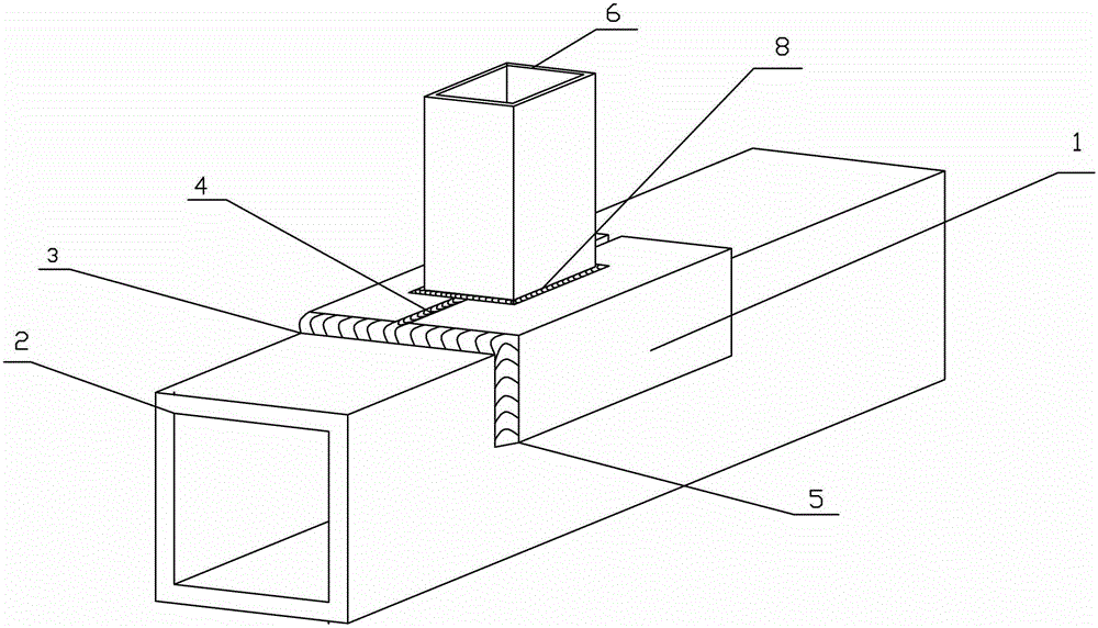
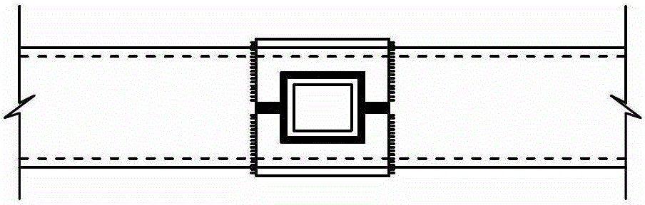
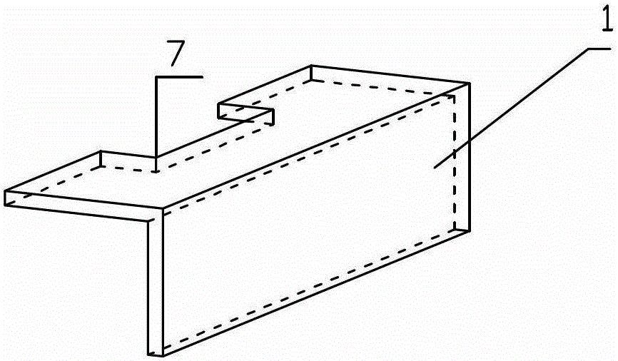
[0016] As shown in the figure: a method for strengthening the ring mouth of a steel pipe node, the ring mouth of the steel pipe node includes the main pipe 2 and the branch pipe 6 of the reinforced node, and the ring mouth is bonded between the main pipe and the branch pipe of the reinforced node by welding Lamination plate 1, an orifice 7 with the same shape as the branch pipe 6 is opened on one side of the ring mouth lamination plate, which is connected by a surrounding weld 8; the ring mouth lamination plate is symmetrically arranged on both sides of the reinforced node, surrounding the branch pipe 6, and will be strengthened The node supervisor is surrounded by 2 halves.

[0017] The main pipe of the strengthened node is connected with the ring joint plate through the side weld 3 and the front surface weld seam 5 ;

[0018] The reinforced node main pipe 2 is a square or rectangular steel pipe; the branch pipe 6 is a rectangular or round steel pipe.

[0019] When the main ...


PUM


Abstract

The invention relates to a method for enhancing a warp angle of a ring mouth flitch of a steel pipe node and belongs to the technical field of construction. The method for enhancing the warp angle of the ring mouth flitch of the steel pipe node is suitable for node reinforcing and repair reinforcing of an existing welded steel pipe structure and machining of an enhanced shaped node of a novel steel pipe structure. The method includes that a ring mouth flitch and the surface of an enhanced joint main pipe are attached and connected through a welding joint. One side of the ring mouth flitch is cut into a hole which is matched with a shape of a branch pipe and welded with the branch pipe. L-shaped ring mouth flitches are symmetrically arranged on both sides of an enhanced node, encircle the branch pipe, and semi-encircle the warp angle of the enhanced node main pipe. The method is suitable for the node reinforcing and repair reinforcing of the existing welded steel pipe structure and machining of the enhanced shaped node of a steel pipe structure, and capable of effectively improving earthquake resistant performance and ductility of a node, improving bearing capacity of the node, ensuring no brittle failure of the welding joint at the root of a steel pipe, and further ensuring good earthquake resistant performance and ductility performance of a space rigid frame or a truss structure.

Description

technical field [0001] The invention relates to a method for reinforcing steel pipe joint rings with plates, which is applicable to joint reinforcement and repair and reinforcement of existing welded steel pipe structures, and is also suitable for processing reinforced joints of newly-built steel pipe structures, belonging to the technical field of construction. Background technique [0002] Steel pipe structures are widely used in towers, bridges, long-span public buildings, medium and high-rise buildings and high-rise structures. Direct welding is one of the most commonly used connection methods between structural members of steel pipes. However, the stress concentration at the weld is obvious and the distribution of residual stress is complex, so there is a great risk of damage. In order to ensure the basic principle of "strong joints and weak members" in steel structures, and to improve the seismic ductility performance of steel pipe structures, it is necessary to streng...

Claims


Application Information

Patent Timeline
Patent Type & Authority Patents(China)
IPC IPC(8): E04B1/58
Inventor 常鸿飞夏军武陆亚萍常虹张风杰魏义波
Owner CHINA UNIV OF MINING & TECH
Why Eureka
Try Eureka