Open-bench blasting method capable of controlling forward stroke of blasting muck pile

A technology of step blasting and pile blasting, which is applied in the blasting field of open-air step blasting to control the blasting pile advance, so as to ensure the safety of mining operations, reduce damage and loss, and improve production efficiency.

Active Publication Date: 2013-02-13
ANSTEEL GRP MINING CO LTD
View PDF3 Cites 21 Cited by
  • Summary
  • Abstract
  • Description
  • Claims
  • Application Information

AI Technical Summary

Problems solved by technology

The first disadvantage is that the forward control ability is small, and the second is that three free surfaces are required
[0008]1 While the open-air step blasting controls the blasting pile forward, it has different degrees of impact on the blasting quality, and there are many large pieces, which affect the efficiency of shoveling operations;
[0009]2 Under the condition that the blasting steps have only two free surfaces, the requirements for better control of the blasting front cannot be met;
[0010]3 The blasting area adopts a blasting sequence method in one blasting, and the reliability of successfully controlling the blasting is low for important parts that require high control distance accuracy

Method used


Image

  • Open-bench blasting method capable of controlling forward stroke of blasting muck pile
  • Open-bench blasting method capable of controlling forward stroke of blasting muck pile
  • Open-bench blasting method capable of controlling forward stroke of blasting muck pile

Examples


Embodiment 1

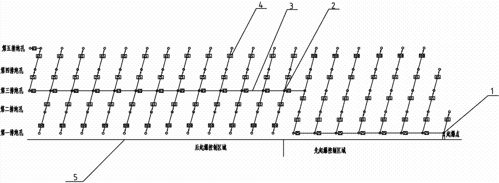
[0040] First carry out the design of deep hole layout and drilling construction. The blasting area is designed with 5 rows, 20 blastholes in each row, triangular holes, hole diameter 250mm, hole spacing 5-8m, row spacing 5-8m, unit step distance 0.5m, hole depth 15m, vertical deep holes, in deep holes The detonating bomb and the detonating detonator are arranged inside, and the time delay of 400ms is adopted in the hole.

[0041] The delayed detonation design of the surface network detonator is carried out according to the following design scheme, the detonator in the blast hole is connected with the surface network detonator and then detonated.

[0042] Delayed detonation design scheme of surface network detonator:

[0043] The first row of blastholes in the first blasting control area is the blasting control row with a 25ms delay between holes, a 65ms delay between rows, and a 100ms delay between rows for the last row of blastholes.

[0044] The middle row of blast holes i...

Embodiment 2

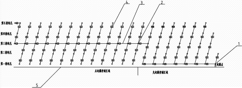
[0046] Such as figure 2 As shown, the deep hole layout design, drilling construction, surface network detonator layout and the delayed detonation design of the surface network detonator in the first detonation area of ​​the present embodiment are the same as in embodiment 1.

[0047] The middle row of blast holes in the rear detonation control area is designed as the blast control row, and the delay time between the holes is 42ms. The delay time between the blast control row and the adjacent fourth row of blast holes is 25ms, and the delay time between the first row of blast holes is 65ms. Delay time, the rest of the rows use a 42ms delay time between rows.

Embodiment 3

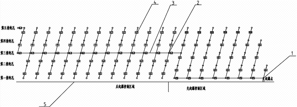
[0049] Such as image 3 As shown, the deep hole layout design, drilling construction, surface network detonator layout and the delayed detonation design of the surface network detonator in the first detonation area of ​​the present embodiment are the same as in embodiment 1.

[0050] The middle row of blast holes in the rear detonation control area is designed as the blast control row, and the delay time between the holes is 42ms. The delay time between the blast control row and the adjacent fourth row of blast holes is 17ms, and the delay time between the first row of blast holes is 65ms. Delay time, the rest of the rows use a 42ms delay time between rows.


PUM


Abstract

An open-bench blasting method capable of controlling a forward stroke of a blasting muck pile comprises the steps of conducting deep hole arrangement, conducting drilling construction, arranging initiation bombs and detonators in deep holes, mounting explosives in the deep holes, conducting detonator delayed initiation design on an earth surface network in the same blasting area, connecting the detonators in the blast holes with detonators of the earth surface network, and initiating the detonators. The method is characterized in that the detonator delayed initiation design of the earth surface network in the same blasting area is that the blasting area is divided into an earlier initiation control area and a later initiation control area which are initiated in sequence, and blasting occurs in the two initiation areas at one time. According to the method, as the blasting area is divided into the two initiation areas, the earlier initiation control area is initiated to provide the later initiation control area with a moving space for containing goods supply and create a free face space condition for the blasting of the later initiation control area. The forward stroke of the blasting muck pile can be controlled precisely and effectively. The safety of the mining operation is ensured, the assistant workload of an electric shovel is reduced, the production efficiency is improved, and the damage and loss caused by the blasting can be reduced.

Description

Technical field: [0001] The invention relates to the technical field of mining, in particular to a blasting method for controlled blasting pile forward in open-air step blasting. Background technique: [0002] Open-air step blasting, also called step blasting, refers to the method of drilling holes on a pre-designed open-air step-shaped excavation surface and loading columnar charges for blasting operations. It is the most widely used blasting method in modern blasting engineering. Large-scale excavations such as open-pit mining, railway and road cutting engineering, hydropower engineering, trench foundation pit excavation, and underground cavern excavation are inseparable from step blasting. [0003] When step blasting is carried out in the open air, the ore and rock to be blasted will move forward to form a loose pile of ore and rock, and the distance moved forward is the forward charge of the blast pile. [0004] The effective control of the front dash of the blast pil...

Claims


Application Information

Patent Timeline
Patent Type & Authority Applications(China)
IPC IPC(8): F42D1/00F42D3/04
Inventor 徐连生杨志富宫长亮樊伟
Owner ANSTEEL GRP MINING CO LTD
Why Eureka
Try Eureka