Two-phase outer cam shock wave rolling transmission internal combustion engine

A technology of shock-rolling movable teeth and external cams, applied in the directions of machines/engines, mechanical equipment, valve drive devices, etc. Small, avoid stuck, reduce the effect of emission

Inactive Publication Date: 2013-02-20
SICHUAN UNIV
View PDF6 Cites 5 Cited by
  • Summary
  • Abstract
  • Description
  • Claims
  • Application Information

AI Technical Summary

Problems solved by technology

Since this kind of internal combustion engine relies on the linear motion of the piston and the plane motion of the connecting rod to press and drive the crankshaft to rotate, there is a large friction between the motion pairs, resulting in low transmission efficiency of the internal combustion engine.
These existing crankshaft connecting rod type internal-combustion engines also have the following main disadvantages: large volume; the unbalanced centrifugal force on the connecting rod and crankshaft is relatively large; the impact is large and the vibration is large; The structure is complex, and it is difficult to process, manufacture, and assemble; in addition, the general internal combustion engine and the transmission device are two independent machines, and usually the internal combustion engine needs to be installed with a transmission for subsequent transmission, resulting in a large volume

Method used


Image

  • Two-phase outer cam shock wave rolling transmission internal combustion engine
  • Two-phase outer cam shock wave rolling transmission internal combustion engine
  • Two-phase outer cam shock wave rolling transmission internal combustion engine

Examples


Embodiment Construction

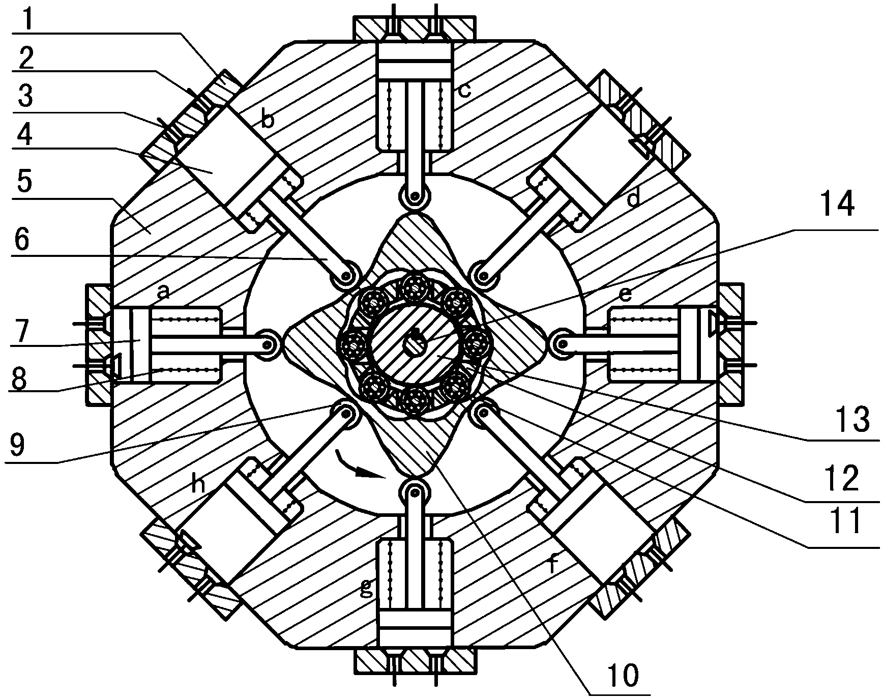
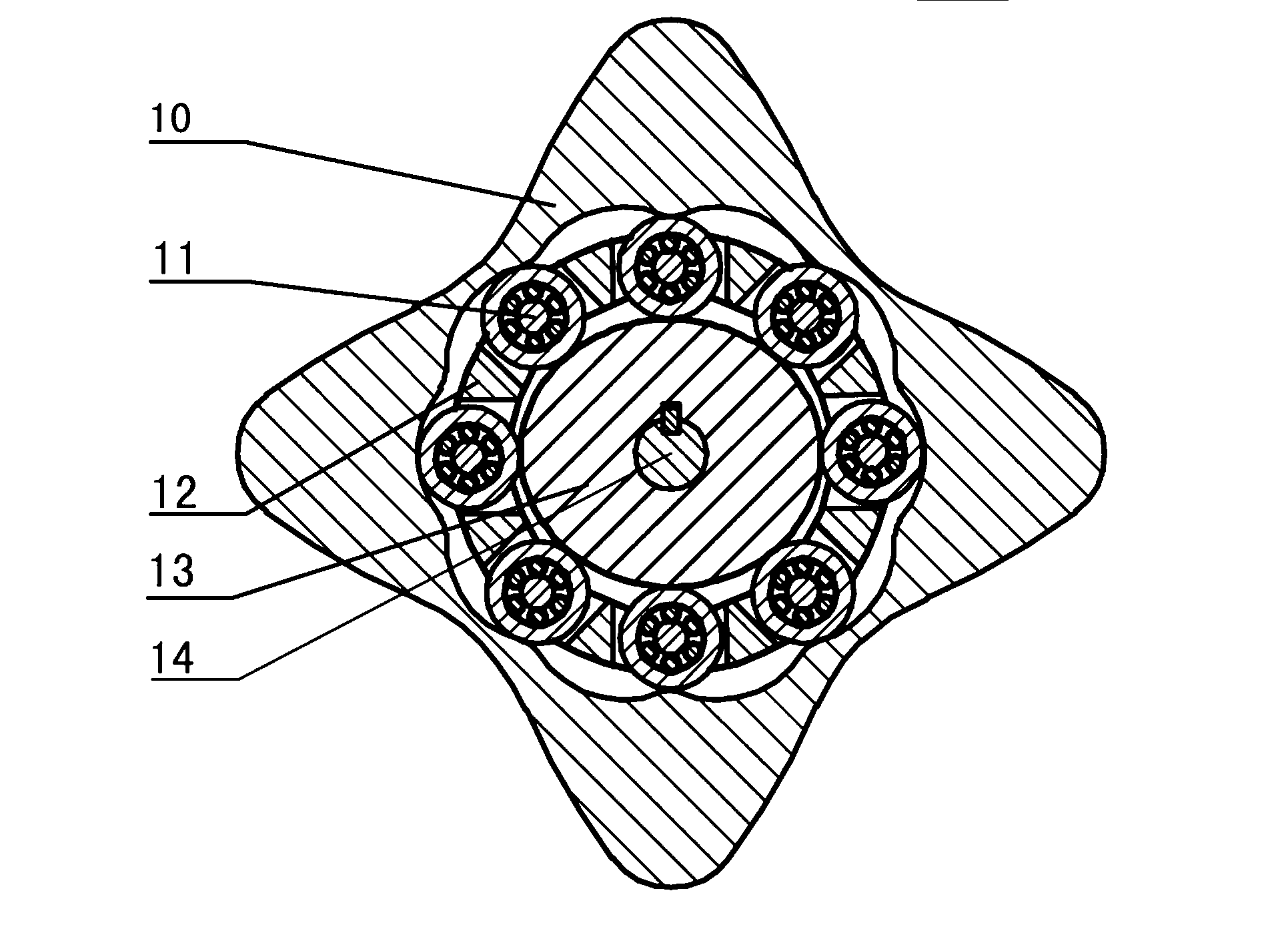
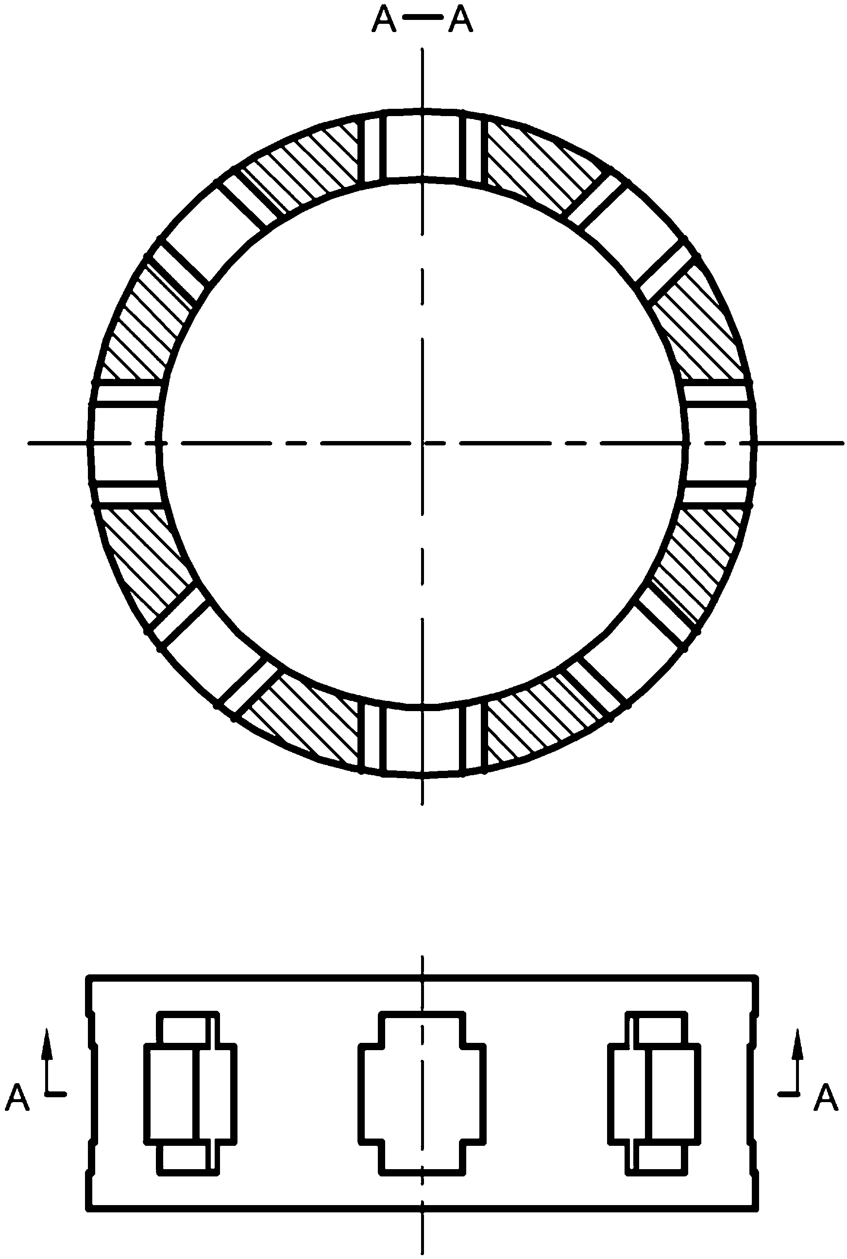
[0040] Figure 1 to Figure 5 The shown two-phase external cam shock wave rolling transmission internal combustion engine consists of cylinder head (1), exhaust valve (2), intake valve (3), cylinder (4), cylinder block (5), push rod (6) , piston (7), spring (8), roller (9), convex inner ring gear (10), rolling movable tooth (11), movable gear rack (12), two-phase external cam (13), output Shaft (14) etc. are formed. The eight cylinders (4) are evenly distributed around the convex inner ring gear (10) in an axially symmetrical manner, and the angle between two adjacent cylinders is 45°. There is a piston (7) in each cylinder (4), and one end of the push rod (6) is consolidated with the piston (7), and the other end is equipped with a roller (9), and the roller (9) makes the push rod ( 6) The connection with the convex inner ring gear (10) is a rolling friction connection. One end of the spring (8) is fixed on the bottom of the piston (7), and the other end is fixed on the boss...


PUM


Abstract

The invention provides a two-phase outer cam shock wave rolling transmission internal combustion engine and relates to the field of gas power. According to the novel internal combustion engine, eight cylinders are annularly symmetrically evenly distributed around a convex inner tooth ring, the resultant force which the convex inner tooth ring is subjected to is zero, and a cylinder piston directly acts on the convex inner tooth ring through a push rod, power is transmitted to an output shaft connected with a two-phase outer cam key by two-phase outer cam shock wave rolling oscillating tooth transmission through the convex inner tooth ring. According to the internal combustion engine, a connecting rod and a crankshaft in a traditional internal combustion engine are not required, a convex inner two-phase shock wave rolling transmission mechanism does not have eccentric mass and has the advantages of self balancing of inertia force and working load, and the rotating speed of the output shaft depends on the transmission ratio of oscillating tooth transmission. If an oscillating tooth brace is fixed, a two-phase outer cam performs high-speed output and can be widely applied to the fields requiring for high rotating speeds, such as helicopter engines and small generators, and discharge of harmful gas can be reduced when the output rotating speed is fixed. The internal combustion engine is simple and compact in structure, small in axial dimensions self-balancing in stress and runs stably.

Description

technical field [0001] The invention relates to the field of gas power, more specifically, a two-phase external cam shock wave rolling transmission internal combustion engine. Background technique [0002] At present, a general internal combustion engine (engine) is composed of a body, a crank connecting rod mechanism, a gas distribution mechanism, a cooling system, a lubrication system, a fuel system, and an ignition system. stroke. The transmission mechanism of this type of internal combustion engine uses a crank-connecting rod mechanism, which transmits the power of the piston to the crankshaft through the connecting rod, and converts the reciprocating linear motion of the piston into the rotary motion of the crankshaft. Because this internal combustion engine presses and drives the crankshaft to rotate by the linear motion of the piston and the planar motion of the connecting rod, there is greater friction between the kinematic pairs, resulting in low transmission effic...

Claims


Application Information

Patent Timeline
Patent Type & Authority Applications(China)
IPC IPC(8): F02B75/22F02B75/40F01L1/08
Inventor 梁尚明贺飞飞柳明辉
Owner SICHUAN UNIV
Why Eureka
Try Eureka