

Mass spectrometer and mass analyzing method
A quality analysis device and quality analysis technology are applied in the direction of measuring devices, material analysis, and material analysis through electromagnetic means, which can solve problems such as poor throughput rate and complicated operation, and achieve the effect of less residue
- Summary
- Abstract
- Description
- Claims
- Application Information
AI Technical Summary
Problems solved by technology
Method used
Image

Examples
Embodiment 2
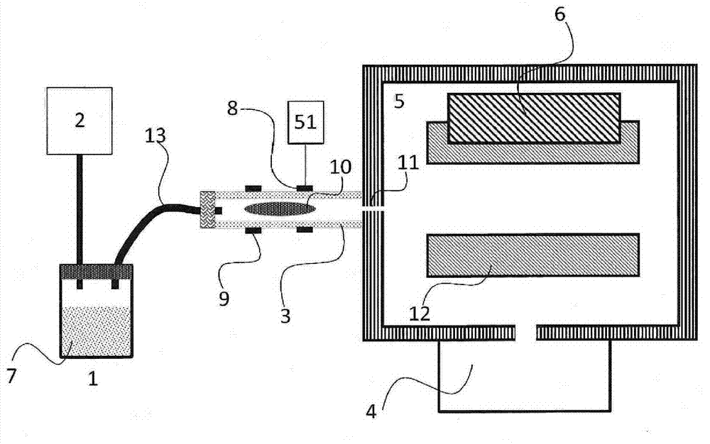
[0050] Image 6 is a configuration diagram showing an example of the mass spectrometer of the present invention. The pressure conditions of the plasma 10 and the output voltage of the power supply 51 are the same as in the first embodiment. Unlike Example 1, a pulse valve 30 is introduced between the ionization chamber 3 and the vial 1, and gas is introduced into the ionization chamber intermittently (discontinuously). When the gas is introduced, the pressure of the ionization chamber 3 temporarily increases, and when the pulse valve 30 is closed, the pressure of the ionization chamber 3 decreases. Therefore, compared with the continuous gas introduction system of Example 1, even if the inner diameter of the pores 11 is increased to increase the flow rate introduced into the vacuum chamber 5, after the pulse valve 30 is closed, the pressure in the vacuum chamber 5 can be maintained at Below 0.1Pa. During the period when the pulse valve 30 is closed, the headspace gas does n...
Embodiment 3
[0056] Figure 9 is a configuration diagram showing an example of the mass spectrometer of the present invention. The pressure conditions of the plasma 10 and the output voltage of the power supply 51 are the same as in the first embodiment. Unlike Examples 1 and 2, the vial pump 2 was connected not to the vial 1 but to the tube 13 . As in Examples 1 and 2, the vial 1 was depressurized to increase the ratio of the sample to the headspace gas. Since the number of pipes connected to the vial 1 is reduced to one, the structure of the vial 1 is simplified, and cost reduction can be expected. On the other hand, since the fresh gas always flows through the tube 13, there is a disadvantage that the adsorption becomes intense.
[0057] In this embodiment, the heater 14 for heating the vial 1 shown in Embodiment 1 can also be applied.
Embodiment 4
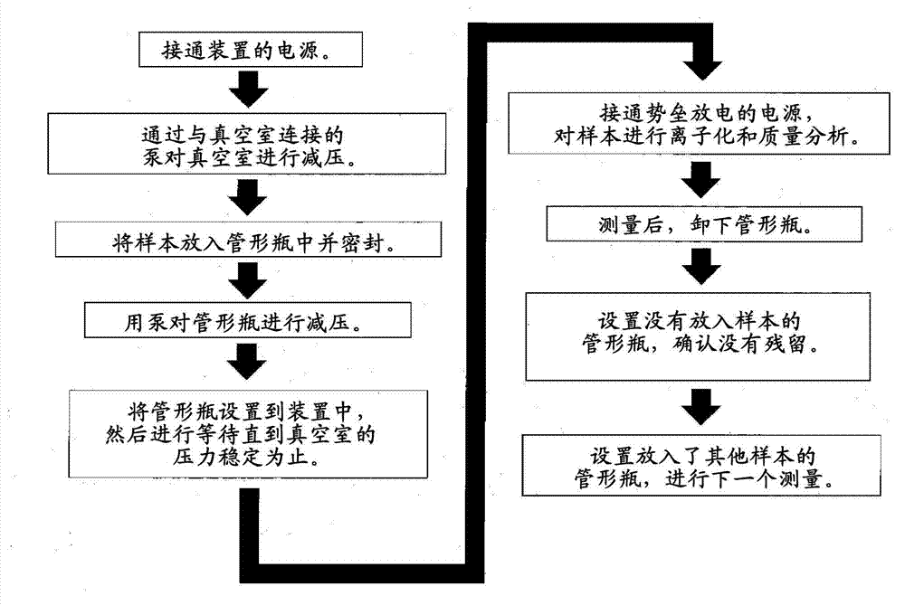
[0059] Figure 10 is a configuration diagram showing an example of the mass spectrometer of the present invention. The pressure conditions of the plasma 10 and the output voltage of the power supply 51 are the same as in the first embodiment. Unlike Examples 1, 2, the pump is not connected to the vial 1 . Figure 11 The measurement flow of Example 4 is shown. It was the same as in Examples 1 and 2 until the sample was injected into the vial 1 and sealed. In Example 4, the vial 1 was not decompressed with a pump, but was directly set in the apparatus with the internal pressure at atmospheric pressure. Then, the pulse valve 30 is kept open for a certain period of time or is opened and closed multiple times in pulses, whereby the vial 1 is depressurized from the vacuum chamber 5 side. The pressure of the vial 1 can be estimated from the value of the pressure gauge attached to the vacuum chamber 5 . When the flow rate generated from the sample solution and the displacement of...
PUM
 Abstract
Description
Claims
Application Information