Porous multilayered filter

A filter and filter layer technology, which is applied in the direction of layered products, chemical instruments and methods, and synthetic resin layered products, can solve the problems of reduced particle collection ability, achieve increased strength, reduced thickness, and prevent filtration performance Reduced effect

Active Publication Date: 2013-03-06
SUMITOMO ELECTRIC FINE POLYMER INC
View PDF5 Cites 9 Cited by
  • Summary
  • Abstract
  • Description
  • Claims
  • Application Information

AI Technical Summary

Problems solved by technology

When damage occurs on the surface of the filter layer, the ability to trap particles is reduced, which is a problem

Method used


Image

  • Porous multilayered filter
  • Porous multilayered filter
  • Porous multilayered filter

Examples


Embodiment 1)

[0126] 18 parts by mass of a liquid lubricant (Supersol FP-25 (ingredient: naphtha) manufactured by Idemitsu Kosan Co., Ltd.) was added to 100 parts by mass of PTFE fine powder (PTFE601A manufactured by DuPont Corporation) and mixed. In a molding machine, the resulting mixture is subjected to compression molding to form a block shaped body.

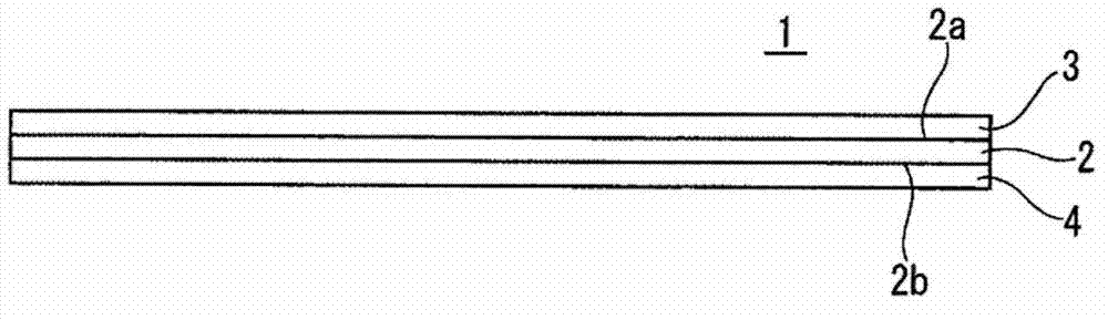
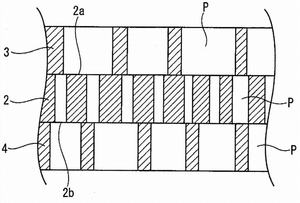
[0127] Next, the block shaped body is continuously extruded into a sheet shape. This sheet-shaped molded body is passed through a press roll, further passed through a heated roll (130°C to 220°C) to remove the liquid lubricant, and wound up on a roll to obtain a 300 μm sheet, which will be used Sheet material that acts to form a filter layer. In addition, a 250 μm sheet was obtained as a sheet for forming a support layer and a protective layer.

[0128] Next, the sheet for forming the filter layer is stretched in the machine direction (machine direction) at a rate of 2 times at a roll temperature of 250°C to 280°C, and then stretched at...

Embodiment 2)

[0134] In order to set the average pore size of the filter layer 2 to 0.05 μm, the stretch ratios of the sheets forming the filter layer in the longitudinal and transverse directions are set like this: as shown in Table 1, the first longitudinal stretch ratio is 2 times, and the first longitudinal stretch ratio is 2 times. Two, the longitudinal stretching ratio is 3 times, and the transverse stretching ratio is 21.5 times. Then, the same procedure as in Example 1 was performed.

Embodiment 3)

[0136] In order to set the average pore size of the filter layer 2 to 0.10 μm, the stretch ratios of the sheet forming the filter layer in the longitudinal and transverse directions are set like this: as shown in Table 1, the first longitudinal stretch ratio is 2 times, and the first longitudinal stretch ratio is 2 times. Two, the longitudinal stretching ratio is 3 times, and the transverse stretching ratio is 21.5 times. Then, the same procedure as in Example 1 was performed.


PUM

PropertyMeasurementUnit
compressive strengthaaaaaaaaaa
thicknessaaaaaaaaaa
thicknessaaaaaaaaaa

Abstract

The purpose of the invention is to protect microfiltration filters so as to prevent damage of the filtration layer. A porous multilayered filter: which is a laminate of three porous drawn PTFE sheets that have been biaxially drawn in the longitudinal and transverse directions; which is obtained from a middle filtration layer, a protective layer that is laminated on the one surface of the filtration layer where the liquid to be processed flows in, and a support layer that is laminated on the other surface of the filtration layer; in which the boundaries between the two surfaces of the filtration layer and the protective layer and the support layer are fused, and the holes of the protective layer and support layer and the holes of the filtration layer communicate with each other three-dimensionally; and in which the mean pore diameter of the holes of the filtration layer is smaller than the mean pore diameters of the holes of the protective layer and the support layer.

Description

technical field [0001] The present invention relates to porous multilayer filters, and more particularly to a microfiltration filter capable of filtering ultrafine particles at high flow rates, in which filter surface protection is achieved. Background technique [0002] Polytetrafluoroethylene (hereinafter referred to as "PTFE") porous filter has characteristics inherent to PTFE (such as high heat resistance, chemical stability, weather resistance, incombustibility, high strength, non-stick properties, and low coefficient of friction) , and has the characteristics of porous bodies (such as flexibility, liquid permeability, particle trapping, and low dielectric constant). PTFE porous filters have been widely used, especially, for microfiltration of liquids, gases, etc. in semiconductor-related fields, liquid crystal-related fields, and food / medicine-related fields due to their excellent characteristics such as high chemical stability filter (membrane filter). [0003] In t...

Claims


Application Information

Patent Timeline
Patent Type & Authority Applications(China)
IPC IPC(8): B01D71/36B01D69/10B01D69/12B32B27/30C08J9/00B32B7/02
CPCB32B2250/242B01D53/228B32B27/322B32B3/26B01D61/147B32B27/08B32B2250/03B01D71/36B32B2305/026B01D69/12B01D67/0027B01D2325/02B32B7/02B32B2307/518B32B2307/724B01D69/10B32B27/30C08J9/00
Inventor 辻胁宽之宇野敦史船津始
Owner SUMITOMO ELECTRIC FINE POLYMER INC
Why Eureka
Try Eureka