Covered stent conveyor and conveying method thereof

A covered stent and delivery device technology, applied in the field of medical devices, can solve problems such as heavy burden on the patient's body, damage to the patient's blood vessels, and failure of the operation, so as to improve the success rate of the operation, enhance the frictional force, and reduce further damage.

Active Publication Date: 2013-03-13
普霖医疗科技(广州)有限公司
View PDF7 Cites 18 Cited by
  • Summary
  • Abstract
  • Description
  • Claims
  • Application Information

AI Technical Summary

Problems solved by technology

[0007] The existing conveyor has the following defects: (1) the front end of the stent-graft is released first, and the stent-graft is prone to shift under the impact force of the blood flow, and is not fixed at the pre-operative predetermined operation position. The operation is declared a failure, and then the patient needs to undergo a thoracotomy for post-processing of the failed operation. During the treat

Method used


Image

  • Covered stent conveyor and conveying method thereof
  • Covered stent conveyor and conveying method thereof
  • Covered stent conveyor and conveying method thereof

Examples


Embodiment Construction

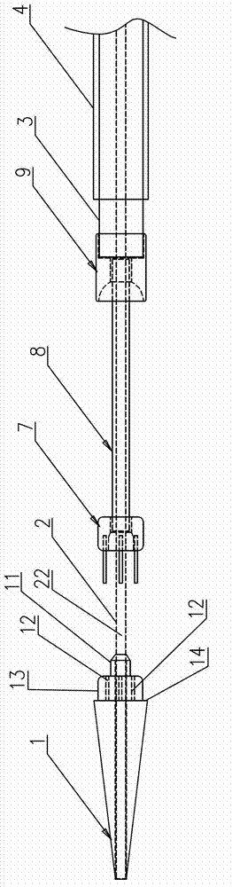
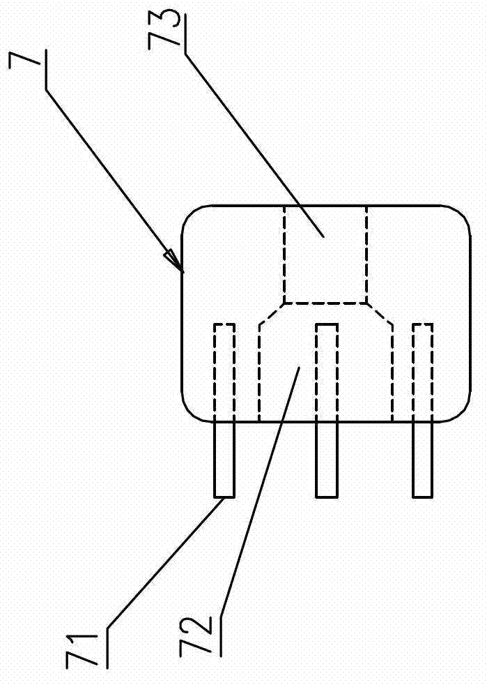
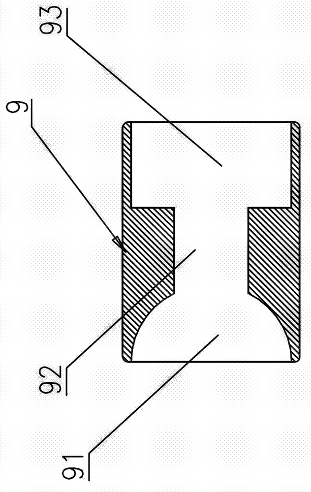
[0040] like Figure 1~6 As shown, it is a stent graft delivery device according to the present invention, which includes a delivery device head 1 and a catheter 2, a shaft tube 3 and a sheath tube 4 which are sequentially socketed from the inside to the outside. As the guide wire channel 22, a bracket fixing head 7 outside the catheter 2 is added between the conveyor head 1 and the shaft tube 3. The bracket fixing head 7 is a cylinder, and the front end of the bracket fixing head 7 is provided with three for The positioning column 71 is set in the coil 51 at the front end of the stent graft 5, and the positioning column 71 is distributed along the circumference of the end surface of the bracket fixing head 7. Correspondingly, the end surface of the tail end of the conveyor head 1 is provided with a positioning hole 12 corresponding to the positioning column 71 , the positioning holes 12 are distributed along the circumference of the end face of the conveyor head 1, and the pos...


PUM

PropertyMeasurementUnit
Bending angleaaaaaaaaaa

Abstract

The invention discloses a covered stent conveyor, which comprises a conveyor head, a catheter, an axle tube and a sheath, wherein the catheter, the axle tube and the sheath are sheathed in sequence from inside to outside; a ring cavity used for accommodating a covered stent is formed between the sheath and the axle tube; a support fixed head externally sheathed with the catheter is additionally arranged between the conveyor head and the axle tube; the support fixed head is a column body; the front end face of the support fixed head is provided with at least two positioning columns sheathed into a coil at the front end of the covered stent; the end face of the tail end of the conveyor head is provided with positioning holes which correspond to the positioning columns; the positioning holes and the positioning columns sheathed in the coil are in close fit; the rear end face of the support fixed head is connected with the front end of the axle tube; the sheath is removed to enable the rear end of the covered stent to be released first; and the conveyor head is pushed to enable the positioning holes to be separated from the positioning columns, so as to enable the front end of the covered stent to be released last. The invention also discloses a conveying method of the covered stent conveyor. According to the covered stent conveyor and the conveying method thereof disclosed by the invention, the reverse release of the covered stent can be realized; and the covered stent is fixed at a preoperative preset operation position, so that the achievement ratio of operation is greatly improved.

Description

technical field [0001] The invention relates to a medical device, in particular to a stent-graft delivery device and a delivery method of the stent-graft delivery device. Background technique [0002] The human thoracic aorta is divided into three parts: the ascending aorta, the aortic arch, and the descending aorta. It is an important vascular channel that connects the heart with the carotid artery, cerebral artery, and abdominal aorta for systemic blood shunting. The vascular channel of the thoracic aorta is relatively tortuous, and the vascular wall bears a large impact of blood pressure. The vascular wall is often damaged by atherosclerotic plaque, infection, cystic necrosis of the middle layer, and trauma, and thoracic aortic aneurysm is easily formed. Once the thoracic aortic aneurysm ruptures, a large amount of blood will be infused into the chest cavity, and the patient's circulating blood volume will be insufficient, resulting in ischemic shock or even death. [00...

Claims


Application Information

Patent Timeline
IPC IPC(8): A61F2/06
Inventor 李妙李林峰曾毅
Owner 普霖医疗科技(广州)有限公司
Why Eureka
Try Eureka