SMT (surface mounted technology) laser stencil and manufacture method thereof

A technology of laser stencil and production method, which is applied in printing, printing plate preparation, printing process, etc., can solve the problems of insufficient solder paste volume, high pollution, high energy consumption, etc., and achieve shortened production process, low roughness, and reduced energy consumption Effect

Active Publication Date: 2013-03-13
SHENZHEN SUNSHINE LASER & ELECTRONICS TECH CO LTD
View PDF8 Cites 3 Cited by
  • Summary
  • Abstract
  • Description
  • Claims
  • Application Information

AI Technical Summary

Problems solved by technology

After the laser template is electropolished, the slag and burrs in the hole wall can be effectively removed, and the roughness of the hole wall is improved, which is conducive to tinning. However, this process has the following disadvantages: high polluti

Method used


Image

  • SMT (surface mounted technology) laser stencil and manufacture method thereof
  • SMT (surface mounted technology) laser stencil and manufacture method thereof
  • SMT (surface mounted technology) laser stencil and manufacture method thereof

Examples


Example Embodiment

[0038] Embodiment one

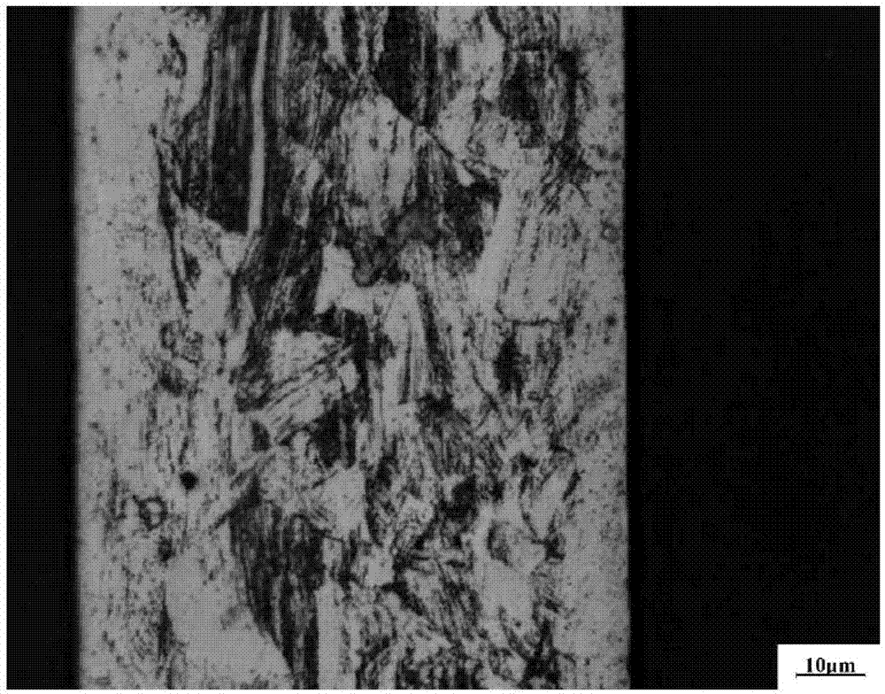
[0039] The weight percentage of each chemical composition in the SMT laser template is: C: 0.0217%, Si: 0.4774%, Mn: 1.471%, P: 0.0296%, S: 0.0017%, N: 0.1105%, Nb: 0.0445%, Ni: 6.809 %, Cr: 17.05%, the rest is Fe and unavoidable impurities. In this example, the thickness of the SMT laser template is 0.12mm, and the grain size is distributed between 1 and 2 μm.

[0040] The tensile strength, yield strength and elongation of the SMT laser template in this embodiment are tested using a computer-controlled electronic universal testing machine CMT5105, and the tensile speed is 3mm / min. The test results are as follows: tensile strength 1180N / mm 2 , yield strength 1100N / mm 2 , The elongation rate is 38.5%; the hardness is tested by Vickers hardness tester MicroMet5103, the load is 3kgf, the holding time is 15s, and three points are tested. The results are 356.3HV, 359.2HV and 360.4HV respectively, and the average value is 358.6HV.

[0041] like figure 1 ...

Example Embodiment

[0042] Embodiment two

[0043]The manufacturing method of the SMT laser template in the first embodiment includes the following steps: (1) After cleaning, laser cutting is carried out according to the requirements of the template graphics; (2) The cut template is placed flat on a grinding platform covered with a thick cloth, Use a grinder equipped with 400~600# fine sandpaper to grind along the opening area formed by cutting; (3) After grinding, use a high-pressure air gun to blow air at the opening area to remove debris (for example, a conventional air compressor can be used The output air pressure is 0.8MPa for blowing to remove debris) to obtain the SMT laser template; (4) Pasting, testing, and shipping.

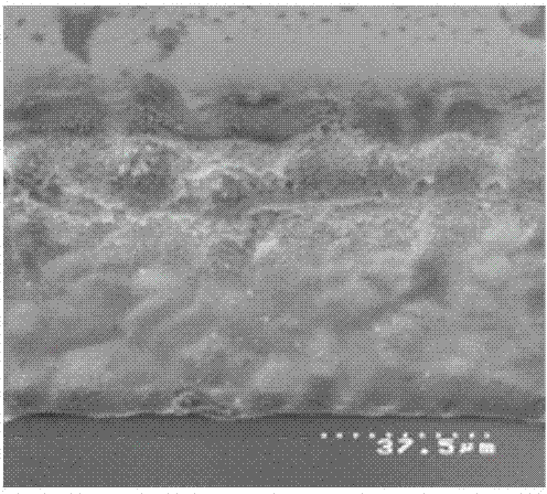
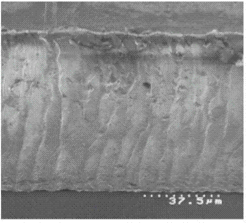
[0044] like image 3 , 4 as shown, image 3 It is the shape of the hole wall after cutting 304 stainless steel by the existing "laser cutting + electropolishing" process, Figure 4 It is the hole wall shape of the SMT laser template cut by the method in this embodim...


PUM

PropertyMeasurementUnit
Grain sizeaaaaaaaaaa
Thicknessaaaaaaaaaa
Thicknessaaaaaaaaaa

Abstract

The invention discloses an SMT (surface mounted technology) laser stencil and a manufacture method thereof. The SMT laser stencil comprises the following chemical ingredients in percentage by weight: no more than 0.03 percent of C, no more than 1.00 percent of Si, no more than 2.00 percent of Mn, no more than 0.04 percent of P, no more than 0.03 percent of S, 0.10-0.16 percent of N, 0.03-0.11 percent of Nb, 6.50-8.00 percent of Ni, 17.00-18.00 percent of Cr, and the remaining is Fe; and the manufacture method of the SMT laser stencil comprises the following steps of: (1) carrying out laser cutting according to the requirement on a stencil drawing; (2) mechanically polishing along a hole arrangement area formed by cutting; and (3) blowing the hole arrangement area to remove scraps so as to obtain the SMT laser stencil. According to the manufacture method of the SMT laser stencil, the effect of laser cutting can be effectively improved, the coarseness of a hole wall is reduced, and the tinning capability of a stencil is improved.

Description

technical field [0001] The invention relates to the field of manufacturing SMT printing templates, in particular to an SMT laser template and a manufacturing method thereof. Background technique [0002] In the SMT (Surface Mounted Technology, abbreviation for Surface Mounted Technology) printing template manufacturing industry, the use of laser cutting to manufacture SMT printing templates (the templates made in this way can be called SMT laser templates, or laser templates for short) has become mainstream. The most commonly used material for laser cutting to make templates is 304 stainless steel, and the grain size is generally 15-30 μm. SMT laser templates use the characteristics of high concentration of laser energy to form openings by melting stainless steel with high-energy laser energy, which results in The SMT laser template has metal slag on the edge of the opening, and the hole wall after cutting is rough and has burrs, which will cause certain difficulties in tinn...

Claims


Application Information

Patent Timeline
IPC IPC(8): B41N1/04B41N1/24B41C1/14
Inventor 蔡志祥侯若洪
Owner SHENZHEN SUNSHINE LASER & ELECTRONICS TECH CO LTD
Why Eureka
Try Eureka