A preparation method of a microwave composite dielectric board and the prepared microwave composite dielectric board

A composite medium and composite medium film technology, applied in chemical instruments and methods, synthetic resin layered products, layered products, etc. The composition is complex and the dielectric constant cannot be further reduced, so as to achieve the effect of eliminating processing limitations, good isotropy of dielectric properties, and good temperature stability

Active Publication Date: 2022-04-29
CHINA ELECTRONIC TECH GRP CORP NO 38 RES INST
View PDF0 Cites 0 Cited by
  • Summary
  • Abstract
  • Description
  • Claims
  • Application Information

AI Technical Summary

Problems solved by technology

However, during the processing and use of this product, due to the rupture of hollow glass beads, the roughness of the metallized hole wall cannot meet the reliability requirements of ≤25um
In addition, the composition of each phase of hollow glass microspheres is complex, and it is difficult to control impurities, which leads to the inability to continue to reduce the dielectric constant and is prone to fluctuations

Method used


Image

  • A preparation method of a microwave composite dielectric board and the prepared microwave composite dielectric board
  • A preparation method of a microwave composite dielectric board and the prepared microwave composite dielectric board
  • A preparation method of a microwave composite dielectric board and the prepared microwave composite dielectric board

Examples


Embodiment 1

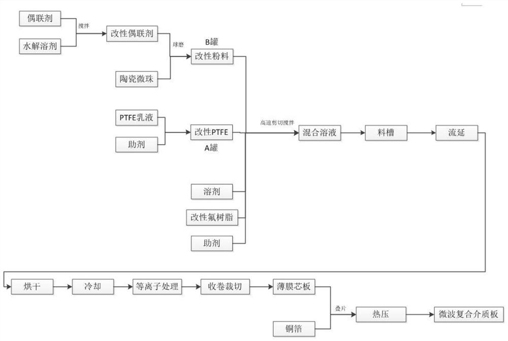
[0032] Such as figure 1 as shown, figure 1 It is a flowchart of the preparation method of the microwave composite dielectric board; the preparation method of the microwave composite dielectric board of the present invention comprises the following steps:

[0033] S1, preparing substrate glue;

[0034] S2, casting: placing the substrate glue prepared in step S1 in a casting machine to obtain a casting film;

[0035] S3, conveying, drying and cooling: the cast film obtained in step S2 is continuously dried through a drying oven, then cooled to room temperature, and the internal stress of the film is eliminated by a tension control mechanism to obtain a microwave composite dielectric film, which is carried out by a winding mechanism. Winding;

[0036] S4, post-processing: performing plasma activation treatment on the microwave composite dielectric film obtained in step S3;

[0037] S5, lamination and lamination: take the microwave composite dielectric film treated in step S4 ...

Embodiment 2

[0065] According to the components specified in Example 2 in Table 1, a low dielectric constant microwave composite dielectric board is prepared, which specifically includes the following steps:

[0066] First add hydrolysis solvent to coupling agent Z-6040, stir evenly, add ceramic microbeads into high-shear stirring tank, stir at 60°C for 1 hour at 100r / min, and transfer to material tank B.

[0067] Add PTFE emulsion and additives into the high-shear stirred tank, stir in the high-shear stirred tank for 1 hour at a speed of 100 r / min, and transfer to material tank A.

[0068] Proportionally, add the modified emulsion, the modified powder, the solvent, the additive, and FEP powder into a 100L high-shear stirring tank in sequence, and stir at 60°C at a speed of 300r / min for 120min , set the vacuum defoaming mode.

[0069] Heat the knife edge of the casting machine to 40°C, transfer the casting film glue to the storage tank of the casting machine, heat the storage tank to 40°C...

Embodiment 3

[0073] According to the components specified in Example 3 in Table 1, a low dielectric constant microwave composite dielectric board is prepared, which specifically includes the following steps:

[0074] First add hydrolysis solvent to the coupling agent Z-6124, stir evenly, add ceramic microbeads to a high-shear stirring tank, stir at 70°C for 1.5h at a speed of 200r / min, and transfer to material tank B.

[0075] Add PTFE emulsion and additives into the high-shear stirred tank, stir in the high-shear stirred tank for 1.5h at a speed of 200r / min, and transfer to material tank A.

[0076] In proportion, add the modified emulsion, the modified powder, the solvent, the additive, and PFA powder into a 100L high-shear stirring tank in sequence, and stir at 70°C at a speed of 400r / min for 75min , set the vacuum defoaming mode. Heat the knife edge of the casting machine to 50°C, transfer the casting film glue to the storage tank of the casting machine, heat the storage tank to 50°C,...


PUM

PropertyMeasurementUnit
thicknessaaaaaaaaaa
densityaaaaaaaaaa
densityaaaaaaaaaa

Abstract

The invention discloses a preparation method of a microwave composite dielectric board and the prepared microwave composite dielectric board, comprising the following steps: preparing a substrate glue; casting: placing the substrate glue in a casting machine to obtain a casting film ;Convey drying and demoulding: drying the casting film through a drying oven and cooling to room temperature to obtain a microwave composite dielectric film; post-processing: plasma activation of the microwave composite dielectric film; lamination matching: use microwave composite dielectric film As the basic unit, it is stacked and matched with the fluororesin film, and the metal foil is placed on the top layer and the bottom layer after the stacking, and vacuum lamination is carried out in a high-temperature laminator to obtain a microwave composite dielectric board; the microwave composite dielectric board prepared by the present invention The dielectric constant of the composite dielectric plate is 1.9-2.0, which can be used in higher frequency bands above the Ku band. The metallized holes are highly reliable, and can be laminated to achieve a higher degree of integration, and the preparation process is stable.

Description

technical field [0001] The invention relates to the technical field of microwave composite dielectric boards, in particular to a preparation method of microwave composite dielectric boards and the prepared microwave composite dielectric boards. Background technique [0002] With the rapid development of 5G communication technology, radar frequency bands are shifting to higher frequency bands. For example, 77GHz automotive radar already belongs to the E-band, and foreign wireless communication companies have targeted the wireless network range to the 60GHz V-band, which carries the microwave composite medium of traditional communication equipment. Substrate materials are all made of electronic grade glass fiber cloth impregnation process. Due to the inherent unevenness of glass fiber cloth, dielectric constant fluctuations are prone to occur when used in frequency bands above 30 GHz, which cannot meet the technical requirements of high-end communication systems. Therefore, a ...

Claims


Application Information

Patent Timeline
Patent Type & Authority Patents(China)
IPC IPC(8): B32B15/00B32B15/085B32B27/06B32B27/18B32B27/32B32B37/10B32B37/12C08J5/18C08L27/18C08K9/06C08K7/18C08L27/20C08L23/08
CPCB32B37/1018B32B37/12B32B27/322B32B27/06B32B15/00B32B15/085B32B27/18C08J5/18C08J2327/18C08J2427/18C08J2427/20C08J2423/08C08K9/06C08K7/18
Inventor 邹嘉佳赵丹殷东平刘建军王璐
Owner CHINA ELECTRONIC TECH GRP CORP NO 38 RES INST
Why Eureka
Try Eureka